GE
HEALTHCARE
D
IRECTION
2307224-100, R
EVISION
6
D
ISCOVERY
LS S
YSTEM
S
ERVICE
M
ANUAL
Chapter 8 - System QC, Calibration and Functional Tests
Page 257
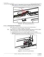
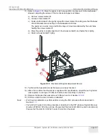
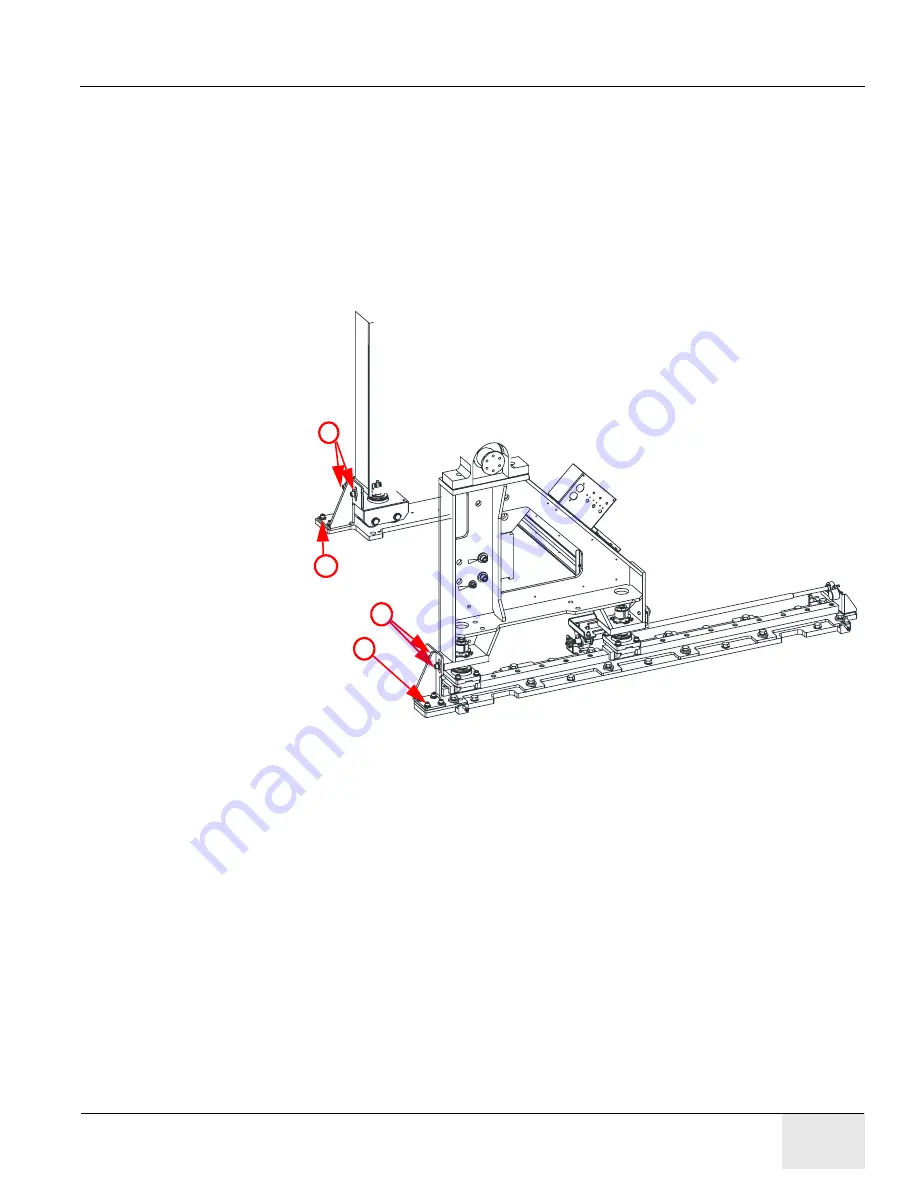
11.) Refer to
. Move the gantry to its home position, and secure it to the mechanical
stoppers, adjusting the screws of the mechanical stoppers as follows:
a.) Remove screws marked
2
.
b.) Loosen screws marked
1
.
c.) Fasten both brackets to the gantry legs with screws marked
3
, making sure that the bases
of both brackets remain resting on the baseplate at all times.
The gantry can now be moved within the range of movement allowed by the oval holes
holding the screws marked
1
.
d.) Move the gantry to enable insertion of the screws marked
2
, and fasten them tightly.
e.) Fasten screws marked
1
tightly.
Figure 8-18:
Mechanical Stoppers Adjustment Screws
12.) Tighten all the baseplate screws that were previously loosened.
13.) After VQC confirms that the Gantry is aligned within specifications, adjust the rear high-load
roller adjuster to a torque of 30 Nm so that the roller rests firmly on the floor.
14.) Replace the bracket that was removed in Steps 3 and 4 of Section
15.) Perform a Well Counter Correction Calibration.
Note:
• Well Counter calibration is performed after running the VQC procedure that is described in
• The full Well Counter Correction procedure is described in the
PET Advance Operator Manual,
Direction 2280383-100
in the sections
: Prepare the Phantom for 2D Well Counter Correction
and
Prepare the Phantom for 3D Well Counter Correction
(if needed).
1
3
2
3

