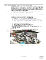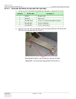
GE H
EALTHCARE
D
IRECTION
2307224-100, R
EVISION
6
D
ISCOVERY
LS S
YSTEM
S
ERVICE
M
ANUAL
Page 132
Chapter 6 - Table
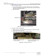
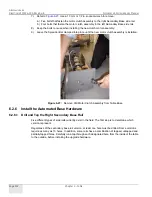
7.) Refer to
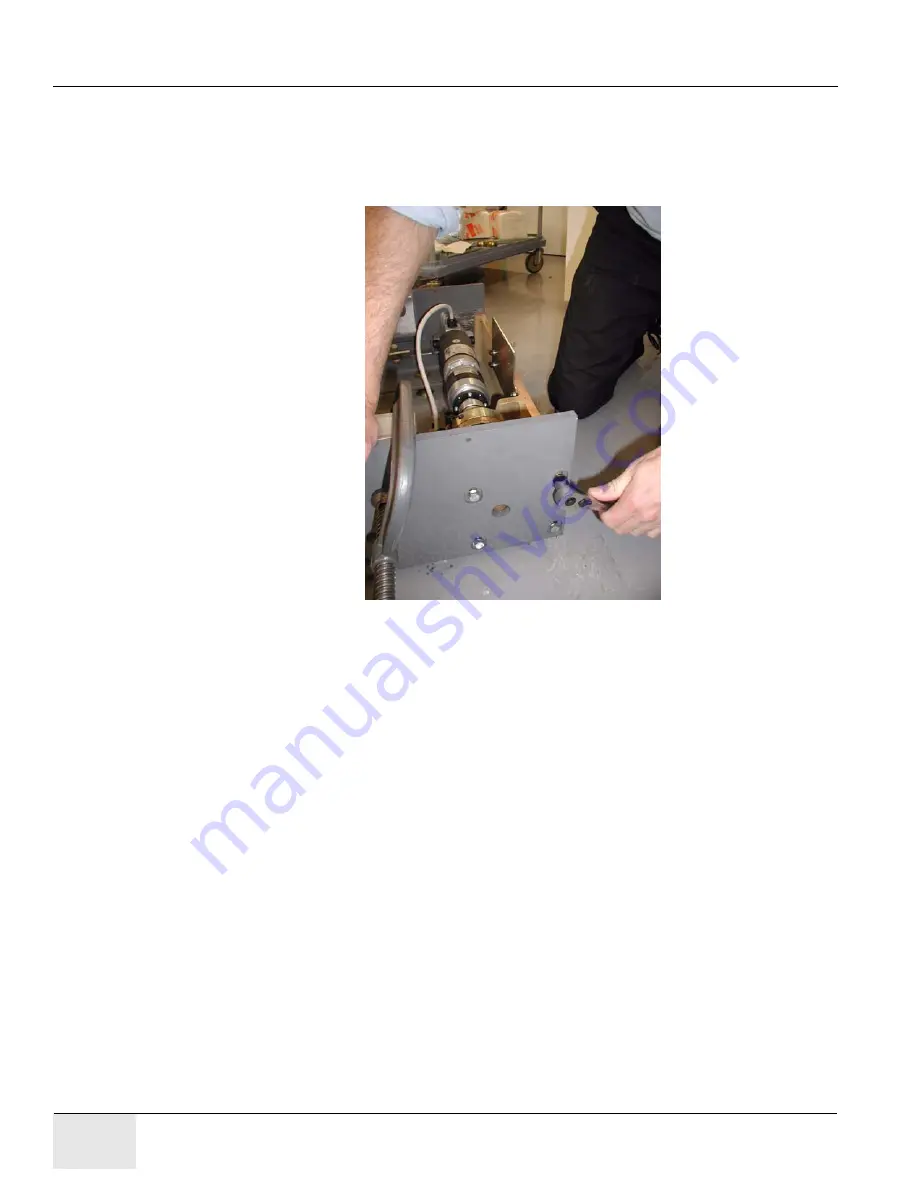
. Use a 13 mm or 1/2 in. socket wrench to remove:
a.) Five bolts that fasten the motor clutch assembly to the right Secondary Base side rail.
b.) Four bolts that fasten the motor clutch assembly to the left Secondary Base side rail.
8.) Keep the bolts to reuse when installing the new clutch motor assembly.
9.) Leave the Spreader Bar clamped into place until the new motor clutch assembly is installed.
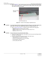
Figure 6-27:
Remove Old Motor Clutch Assembly from Table Base
6.2.6 Install the Automated Base Hardware
6.2.6.1 Drill and Tap the Right Secondary Base Rail
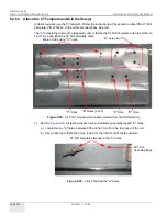
Five different types of side rails currently exist in the field. The first step is to determine which
version is present.
Regardless of the secondary base rail version, at least one hole must be drilled. Some versions
require as many as 13 holes. In addition, some rails have a combination of tapped, untapped and
partially tapped holes. Carefully run a tap through each designated hole, from the inside of the table
to the outside, before installing the upgrade hardware.


