GE H
EALTHCARE
D
IRECTION
2307224-100, R
EVISION
6
D
ISCOVERY
LS S
YSTEM
S
ERVICE
M
ANUAL
Page 142
Chapter 6 - Table
5.) Vacuum all debris from the area.
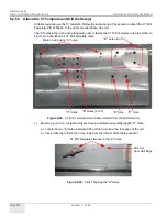
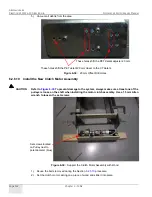
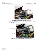
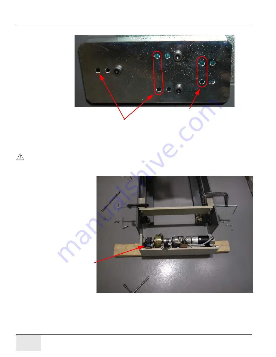
Figure 6-38:
20 mm Offset Drill Holes
6.2.6.10 Install the New Clutch Motor Assembly
CAUTION
Refer to
To prevent damage to the system, always make sure at least one of the
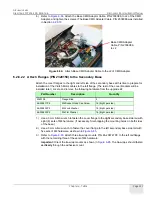
pulleys is loose on the shaft when installing the motor clutch assembly. Use a 1.5 mm Allen
wrench to loosen the set screws.
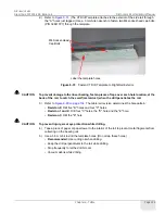
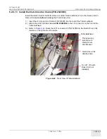
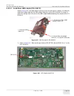
Figure 6-39:
Support the Clutch Motor Assembly with Wood
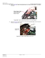
1.) Reuse the bolts removed during the Section
procedure.
2.) Set the clutch motor casting on a piece of wood and slide it into place.
These holes shift the PET detent 20 mm closer to the CT detent.
These holes shift the PET detent adjuster 20 mm.
Set screws located
on Pulley next to
potentiometer (blue).


