GE
HEALTHCARE
D
IRECTION
2307224-100, R
EVISION
6
D
ISCOVERY
LS S
YSTEM
S
ERVICE
M
ANUAL
Chapter 8 - System QC, Calibration and Functional Tests
Page 253
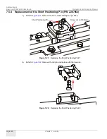
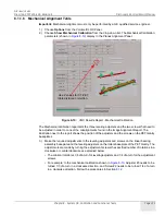
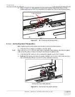
2.) Refer to
. After adjustment, make sure that the Z Adjustment Screw is firmly
positioned against the PET Positioning Block, and tighten the three screws loosened earlier.
Figure 8-11:
PET Positioning Block Adjustment
8.1.2.2 Gantry Alignment Prerequisites
Before performing the gantry alignment procedures, perform the following steps:
1.) Verify that the two dollies are installed on the PET gantry.
Note:
Make sure a 2 in. x 2 in. x 30 in. wooden block is available to place between the dolly and gantry
while raising the gantry to prevent bending of the dolly into the gantry's side.
2.) Verify that the PET Gantry is in its normal working position next to the CT Gantry.
3.)
Optional:
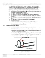
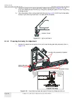
If the driving mechanism is already installed, remove the 4 x M6 screws securing
the holding bracket (shown in
) from inside the rear beam.
Figure 8-12:
Driving Assembly Holding Bracket
Loosen 3 screws.
Z Adjustment Screw
Locking Nut
Driving Assembly Holding Bracket


