GE H
EALTHCARE
D
IRECTION
2307224-100, R
EVISION
6
D
ISCOVERY
LS S
YSTEM
S
ERVICE
M
ANUAL
Page 276
Chapter 10 - Electrical Connections
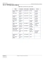
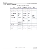
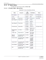
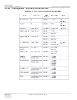
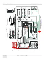
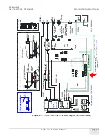
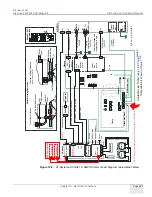
Figure 10-3:
CT System with GOC1 & CPDU Interconnect Diagram (Manual Tables)
Ta
bl
e
J1
J2
J9
J1
0
J1
1
J1
2
J1
3
E
TC
P
a
n
el
T ab
le
M oto
r
K B
B ox
J5
2
J2
0
Ga
nt
ry
†
S
h
ie
ld
s
g
ro
u
nd
ed
w
it
h
cl
a
mp
a
t
gan
tr
y
b
a
se
.
J7
Po
we
r
Pa
ne
l
S
can
L
A
N
Tr
a
n
s
ce
iv
e
r
Host
C
o
m
p
ute
r
L
AN
DA
S
D
at
a
(F
ib
e
r)
Sc
a
nI
N
T
L(
In
te
rl
o
ck
)
Co
n
so
leP
ow
e
r
Co
n
s
ol
e
DASM
O
ption
Hosp
ital
N
e
twork
P
ow
e
r
Pa
n
(D
et
a
il
B
)
S
yst
e
m
Gr
o
u
nd
Bu
s
Va
ul
t
Gr
o
u
n
d
b
ra
id
e
d
g
n
dc
a
b
le
J8
S
TC
Ba
ck
p
la
n
e
(D
e
ta
il
C
)
†
P
ow
e
r
Pa
n
Bu
lkh
ea
d
(D
e
ta
il
B
)
G
ro
un
d
J2
1
2
3
GN
D
L
ug
De
ta
il
B:
Ga
n
tr
y
P
ow
er
P
an
HVDC
Pwr
123
Ax
ia
lM
tr
P
ow
e
r
Fr
o
n
t
Vi
ew
:B
ul
kh
ea
d
B
NC
(M
in
i
B
N
C
b
eh
in
d)
L
AN
(D
AS
b
e
hi
nd)
To
p
V
ie
w,
in
cl
ud
in
gB
u
lk
h
ea
d
(H
V
D
Co
mi
tt
e
d
fo
rc
la
ri
ty
)
123
LA
N
DA
S
(f
ib
er
)
Ax
ia
l
M
tr
P
wr
BNC
M
in
iB
N
C
12
0
VA
C
P
ow
e
r
Sc
a
n
Di
s
p
la
y
C
on
so
le
M
oni
to
rs
Cl
a
m
p
s
Cl
a
m
p
De
ta
il
C
:S
T
C
Ba
c
kpl
a
n
e
J7
J8
S
CI
M
Tr
a
c
kb
al
l
J1
9
Ph
o
n
e
L
ine
K
e
y
b
o
a
rd
1
2
2
27
5
58
4
-2
#
2G
ro
u
n
d
Re
tr
a
c
tor
J1
1
J
1
2
J1
3
Ta
bl
e
IF
2
2
710
5
9-
J
17
S
TC
Bac
k
p
la
n
e
1
20
V
AC
2
265
68
3-
Ti
lt
R
el
a
y
B
d
2
26
3
66
3
T
ilt
Li
m
it
Sw
.
2
2
6
8
22
2
LA
N2
2
6
5
88
1
-2
J4
J3
J2
J1
J1
0
J9
J5
S
eco
nda
ry
B
a
se
1/
0g
n
d
1
/0g
n
d
Br
a
id
e
dG
N
D
ca
bl
e
2
2710
60
21
17
848-
2
2266
887
Co
nt
ro
l
2266
014
HV
DC
P
o
we
r
HV
DC
Ax
ia
l
M
tr
P
o
we
r
1
2
0
VA
C
P
ow
e
r
1/
0
g
nd
2
27
5
84
4
†
SCSI
T
o
wer
(GOC1)
De
vice
1
De
vice
2
Recon
Box
(GOC1)
GOC1
(Global
Operator
Console)
=
P/N
2341104-2
or
2341923-2
233
5376
TS
1-1
TS
2-1
CP
DU
J5
22
6764
2
22
6764
4
2
2
6
6
880
J4
CPDU
=
P/N
2269902
A
d
et
a
ile
d
v
ie
w
o
f D
is
co
ve
ry
L
S
C
T
c
a
bl
e
s
is
s
h
ow
n
in

