

Summary of Contents for Eagle 1000
Page 1: ...Eagle 1000 Patient Monitor Servicing Instructions 227 468 01 SA e Revision G ...
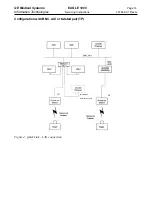
Page 121: ......
Page 122: ......
Page 123: ......
Page 124: ......
Page 125: ......
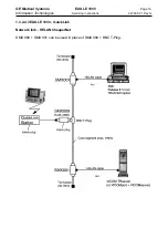
Page 130: ......
Page 135: ......
Page 136: ......
Page 138: ......
Page 141: ......
Page 142: ......
Page 143: ......
Page 144: ......
Page 145: ......
Page 146: ......
Page 147: ......


