background image

GE Zenith Controls

3

Entelli-Switch 250 Operation and Maintenance Manual (71

R

-2000)

Each GE Zenith transfer switch is factory wired and 
tested. A complete information package is furnished
with each switch which includes:

a.

Sequence of operation.

b.

Description and operation of 
all accessories supplied.

c.

Power panel connection diagram 
and schematic.

d.

Description and identification of 
all customer field connections.

Installation of GE Zenith transfer switches includes:

a.

Mounting the transfer switch cabinet.

b.

Connection of Source 1, Source 2, 
and Load cables or bus bars.

c.

Connection of external control 
circuits as required.

Safety / Installation

DANGER

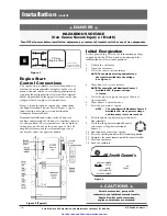
HAZARDOUS VOLTAGE

(Can Cause Severe Injury or Death)

Turn OFF all power before installation, adjustment, or removal of transfer switch or any of its components.

The safe operation of your switch is 

GE

Zenith’s focus.

The proper storage, installation, operation and mainte-
nance will help increase the life of the switch.

Equipment Inspection
and Storage

Once you have received the transfer switch, inspect
it for any damage. This includes damage to the
enclosure, power panel, control panel and wiring
harness. If any damage is found or suspected, file a claim
as soon as possible with the carrier and notify the nearest

GE

Zenith representative.

Before installation, if it is necessary, store the transfer
switch in a clean dry place, protected from dirt and
water. Provide ample air circulation and heat, if neces-
sary, to prevent condensation.

5% to 95%

(non-con-

densing)

-30°C to

+75°C

(-22°F to

+167°F)

40-400 

AMP

(molded shell)

-20°C to +65°C

(-4°F to +149°F)

40-4000 

AMP

(all other frame 

and panel types)

-20°C to +60°C

(-4°F to +140°F)

Operating

Storage

Temperature

Temperature

(Ambient):

Humidity

CAUTION

Due to hazardous voltage and current, 

GE

Zenith rec-

ommends that a 

GE

Zenith Certified technician or a

qualified electrician must perform the

installation and maintenance of the switch.

WARNING

Do not use a blower since debris may 

become lodged in the electrical and 

mechanical components and cause damage.

Final Equipment Inspection

Prior to energizing the transfer switch:

1.

Remove any debris incurred, with a vacuum, due
to shipment or installation.

2.

Verify that all cabled connections are 
correct and that phase rotation of both sources
match.

3.

Check engine start connections.

4.

Verify the correct connection of all 
control wires.

5.

Check settings of all timers and adjust 
as necessary.

6.

Adjust any optional accessories as required.

7.

Check the lug torque values of the power 
connections.

NOTE

:

Lug torque values are specified 
in the power panel manual.

8.

Make sure that all covers and barriers are
installed and properly fastened.

NOTE

:

Power panels ship from GE Zenith 
in Source 1 Position.

Table 1

Get other manuals https://www.bkmanuals.com

Summary of Contents for Entelli-Switch 250

Page 1: ...71R 2000 5 03 Operation and Maintenance Manual Entelli Switch 250 Microprocessor Controller Transfer Switch Control Panel GE Zenith Controls e Get other manuals https www bkmanuals com...

Page 2: ...Authorized Service For GE parts and service call 773 299 6600 GE Zenith Transfer Switches are used to provide a continuous source of power for lighting and other critical loads by automatically transf...

Page 3: ...ntative Before installation if it is necessary store the transfer switch in a clean dry place protected from dirt and water Provide ample air circulation and heat if neces sary to prevent condensation...

Page 4: ...with the ATS and read and understand the information on all accessories provided 1 Unlock the enclosure 2 Open the enclosure 3 Verify the correct system voltage NOTE The equipment rating nameplate on...

Page 5: ...w these steps to set up the ATS Refer to Entelli Switch 250 display Figure 4 The annunciation LEDs illuminate to indicate 1 source availability 2 ATS position and 3 Entelli Switch 250 control function...

Page 6: ...evere Injury or Death Turn OFF all power before installation adjustment or removal of transfer switch or any of its components To R T Box To Power Panel Input Output Connectors to I O Modules Engine S...

Page 7: ...n the exterior of the door see figure 7 1 User accessibility to the following a LED indication of source availability b LED indication of transfer switch position c LCD screen indicates 1 timer count...

Page 8: ...which screen is being displayed 2 or the word on the LCD above the key The word above the key changes depending on which screen is being displayed 3 or the word on the LCD above the key The word above...

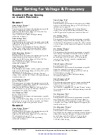
Page 9: ...transfer to Source 2 Adjust via the SET menu Range is 85 to 100 in 1 increments see page 18 Once satisfied the W timer will begin timing to transfer to Source 2 Under Voltage Fail Factory Default 80 T...

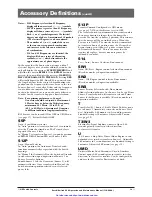
Page 10: ...S SENS SPES PSGS 2 2 2 2 2 2 2 2 3 3 2 2 2 2 2 2 2 2 2 2 2 2 Group Packages 2 2 3 Standard Accessory included in the group package Optional Accessory not included but can be added to group package Opt...

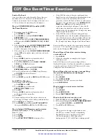
Page 11: ...simulate a power failure start Generator and run under load Can be configured by end user for 1 7 14 28 365 day cycle See page 16 CDT Load or NO Load One event exerciser with adjustable Engine exerci...

Page 12: ...iming to signal the Generator to start Source 1 Over Voltage Restore Factory Default 105 This adjustment determines the minimum acceptable over Voltage threshold at which the Transfer Switch is allowe...

Page 13: ...Transfer Switch functions automatically as specified with the Switch drawings In Manual the Automatic Transfer Switch will transfer to either direction upon depression of Source 1 or Source 2 transfe...

Page 14: ...nter this value and compete the clock setting 17 To edit settings press SEL and repeat steps 6 16 18 If the setting is satisfactory press MORE unit then returns to the SET menu then press BACK then ES...

Page 15: ...iate Test If the CDT Exerciser is Factory configured for a Load Exerciser the Controller will immediately start a load exercise The controller will start the generator transfer the load to Source 2 an...

Page 16: ...select DAILY WEEKLY 14 DAY 28 DAY or 365 DAY as desired 9 Press SAVE 10 Press MORE repeatedly to BACK then ESC to S1 OK screen How to set SET the DAILY Exerciser 1 Beginning from the S1 OK screen pre...

Page 17: ...located on the back of the controller Network Communications Option 11 12 13 R1 Output 5 6 7 R1 Output 14 15 16 R2 Output 8 9 10 R2 Output Contact Rating 10A 277VAC or 30VDC 1 2 3 4 5 6 7 8 9 10 11 12...

Page 18: ...hange adjustable values through the SET menu Enter six digit access code The factory assigned six digit access code is located on the back of the controller Figure 10 Network Communications Option 11...

Page 19: ...Output 8 9 10 R2 Output Contact Rating 10A 277VAC or 30VDC 1 2 3 4 5 6 7 8 9 10 11 12 13 14 15 16 PROG 1 PROG 2 GRD Input Sink LS OUT NIA OUT ELEV PRE OUT ALARM OUT STE OUT MOTOR DISC OUT TMS IN INHI...

Page 20: ...nto the Source 2 Deactivating the test switch will start retransfer to Source 1 The switch will complete its retransfer to Source 1 after the time delay of the T timer The U engine overrun timer allow...

Page 21: ...frequency stabilization before retransfer A manual pushbutton BYPASS is provided to bypass the T time delay if desired After the T time delay the CCN relay energizes the CN solenoid to retransfer the...

Page 22: ...only after the controller ensures the proper phase relationship between the two Sources After the ATS closes into Source1 the SN limit switch becomes activated to de energize the CCN relay and energi...

Page 23: ...handle in its holder and the service access cover on the left side of the transfer switch 11 Re connect the transfer switch to AUTO b Auto Location Removal of the closed transition transfer switch if...

Page 24: ...t to Source 2 When Source 2 voltage and frequency reach the preset Restore values the time delay to open Source 1 timer W begins its timing cycle to ensure voltage and frequency stabiliza tion before...

Page 25: ...the two Sources After the ATS closes into Source1 the SN limit switch becomes activated to de energize the CCN relay and energize the CCEO relay which opens the ATS out of Source 2 The SEO limit swit...

Page 26: ...art No Description Qty 1 See Chart Transformer 1 VA 2 2 See Chart Transformer 25 VA 2 3 K 1274 Relay Flange Mounted 2 Bill of Material R T Box Primary 1 VA 25 VA Assembly Voltage XFMR XFMR Part No at...

Page 27: ...24 50P 1035 208 220V K 3217 K 3225 50P 1036 230 240V K 3218 K 3226 50P 1037 277V K 3219 K 3227 50P 1038 380 400V K 3220 K 3228 50P 1039 416 440V K 3221 K 3229 50P 1040 460 480V K 3222 K 3230 50P 1041...

Page 28: ...UT 18 1 3 PHASE SOURCE 2 SENSING 10V XE2 32 907 StandardTransition R T Box Schematic GND 903 902 801 901 807 804 803 904 905 906 805 806 CCEO COIL CONTROL RELAY OPEN SOURCE 2 CCNO COIL CONTROL RELAY O...

Page 29: ...ency not within acceptable parameters Power supply connector unplugged Check utility and utility breakers Plug in connector GeneralTroubleshooting The following troubleshooting guide is used to recogn...

Page 30: ...ear service cycle The battery maintains the exerceser memory only and does not otherwise affect the operation Testing A manual operator handle is provided with the transfer switch for maintenance purp...

Page 31: ...GE Zenith Controls 31 Entelli Switch 250 Operation and Maintenance Manual 71R 2000 Get other manuals https www bkmanuals com...

Page 32: ...t of GE Industrial Systems General Electric Company 830 West 40th Street Chicago IL 60609 USA 773 299 6600 Fax 773 247 7805 www geindustrial com g GE Zenith Controls Get other manuals https www bkmanu...

Reviews: