4.4-01
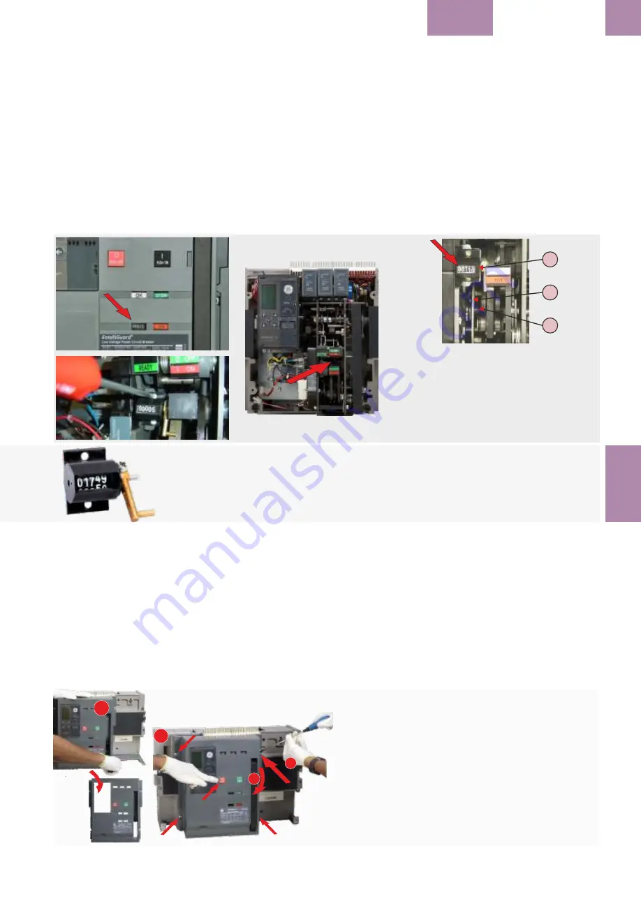
4.4.1 LICZNIK OPERACJI
Opcjonalny licznik operacji jest dostarczany
ze
śrubami
do jego zamocowania. Licznik jest
mocowany w
ewnątrz
mechanizmu
wyłącznika
.
Zlicza on i
wskazuje liczbę
wszystkich zazbroje
ń
wyłącznika. Jest również dostępny w wersji do
zabudowy fabrycznej.
Uwaga:
Nie jest możliwe wyzerowanie wskazań
licznika.
1. Usunąć płytę czołową wyłącznika według
wskazówek podanych w innych rozdziałach.
2.
Przyłożyć
mechaniczny licznik operacji do
dwóch otworów we wsporniku w mechanizmie
,
sprawdzając czy wskaźnik liczbowy będzie
widoczny w okie
nku w płycie czołowej
wyłącz
nika.
3. Sprawdzić, czy dźwignia sterownicza (B)
licznika jest połączona z cięgnem (A) sprężyny
mechanizmu napędowego wyłącznika i czy
porusza się swobodnie.
4. Zamocować licznik używając dostarczonych
śrub, przykręcając je momentem 2,5 -3 Nm.
4.4.1 CONTADOR DE OPERAÇÕES
Um pacote adicional contém um contador de
operações com parafusos de fixação. A unidade
colocada dentro do mecanismo do disjuntor. Ela
indica e conta cada operação de carregamento
do mecanismo do disjuntor. Também está
disponível uma variante de montagem em
fábrica.
Nota:
O Contador de operações não pode ser
reposto a 0.
1. Remova a face/Cobertura do Disjuntor como
já anteriormente explicado.
2. Posicione o contador de operações
mecânicas (Fig.) sobre os dois furos existentes
dentro do braço do mecanismo, garantindo que
a sua face de leitura está alinhada com a
abertura para visualização.
3. Garanta que o braço de operação do (B)
contador Está conectado ao mecanismo de
carregamento de bobina (A) do disjuntor e que
está corretamente posicionado e operando
livremente.
4. Monte nessa posição usando os parafusos
incluídos e aplique um torque de 2,5-3 Nm.
4.4.1 OPERATIONS COUNTER
The optional pack contains an operations
counter with fixing screws. The unit is fitted to
the inside of the circuit breaker Mechanism. It
indicates and counts each charging operation of
the Breaker mechanism. It is also is available in a
factory mounted variant.
Note:
The Operations Counter cannot be reset.
1. Remove the Breaker fascia/Front Cover as
explained elsewhere in this section.
2. Position the mechanical operations counter
(Fig.) over the two holes provided inside the
mechanism bracket, ensuring the indicator face
is aligned to show through the window in the
cover.
3. Ensure that the operating arm (B) of counter is
linked with the spring charging link (A) of the
breaker mechanism and that is correctly
positioned so that it operates freely.
4. Mount in position using the screws provided
and apply torque 2,5-3Nm.
Instruction sheet
Folha de Instruções
Instrukcja
EntelliGuard L
ACCESSORIES
4
.4
C
OUNTER
Catalogue Numbers
Factory mounted
Field kit or Spare
Número de Catálogo
Montado em Fábrica
Kit Campo ou Sobressalente
Numer katalogowy
I
nstalacja fabryczna
część zamienna
--------------------------------------------------------------------------------------------------------------------------------------------------------
Counter
GMCN
GMCNR
Contador
Operations Counter Location
A) Spring charging link
B) Operating arm
C) Operations Counter
Local do Contador de operações
A) Ligação de carrgeamento das
molas
B) Armadura de operação
C) Contador de operações
Miejsce zamocowania licznika
A) Cięgno sprężyny napędu
B) Dźwignia sterownicza
C) Licznik operacji
A
B
C
Removal of Front cover
1
. Remove pad locks, installed if any. Switch off the breaker.
2.
Unscrew the 4 screws (6Nm, 4.42ft-lbs) using a Pozidrive screw driver as shown in
Fig. A&B.
3.
Rotate the charging handle down and slide the front cover over the handle to
remove out as shown in Fig. C.
Remoção de Frontal / Cobertura Frontal do disjuntor
1.
Remova os cadeados, se instalados. DESLIGUE o disjuntor.
2.
Desaperte os 4 parafusos usando uma chave Pozidrive como mostrado na Fig. AeB.
3.
Rode para baixo a alavanca de carregamento e puxe a face frontal deslizando pela
alavanca para remover como mostrado na Fig. C
Usunięcie płyty czołowej
1.
Usunąć kłódki, jeśli są założone
. Wyłączyć wyłącznik.
2.
Odkręcić
4
śrub
(6Nm)
używając wkrętaka
Pozidrive w sposób pokazany na Fot. AiB.
3
.
Obrócić korbę w dół i przesunąć płytę czołową nad dźwignią aby zdjąć ją w sposób
pokazany na Fot.
C.
A
B
C
C


