CHAPTER 9: PROGRAMMING GROUP 0 – GLOBAL METER SETUP
48
EPM 5000 series Advanced Power Meters
GE Multilin
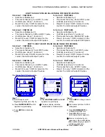
OPEN DELTA SYSTEM INSTALLATION PROGRAMMING
A special switch is used to indicate that the electrical system being monitored is a Three-phase WYE or
Three-Wire Open Delta System using the connection installation (see Chapter 3). The switch is located in
GROUP 0, FUNCTION
3
, Pack 1, Switch D.
WARNING:
This switch should be set to UP only if the electrical system is a Three-Wire Delta or Open
Delta, using 2 PTs. Otherwise, the switch should be set to DOWN. Failure to select this switch results in
Phase-to-Neutral readings, as well as incorrect power readings, with the 2PT connection.
Special Open Delta Connection Installation should be followed in the Installation and Operation section
(Chapter 3).
SWITCHING COMMUNICATION PROTOCOLS, EI-BUS, MODBUS RTU/ASCII, DNP 3.0
•
For EI-BUS protocol: PACK
2,
Switch C is DOWN, Switch D is DOWN.
•
For MODBUS protocol, ASCII framing: PACK
2,
Switch C is UP, Switch D is UP.
•
For MODBUS protocol, RTU framing: PACK
2,
Switch C is DOWN Switch D is UP.
•
For DNP 3.0 protocol: PACK 2, Switch C is UP, Switch D is DOWN.
NOTE
: When programming for MODBUS protocol configuration of LIPA (Long Island Power Authority)
mapping options may be performed through communication.
9.5 Modbus Plus Capability
When using the MPI Modbus Plus adapter, the meter values should be set to speak to Modbus RTU with
a meter address of 0001 and a baud rate of 9600 baud. The Modbus Plus address is programmed into
the MP1 Modbus Plus adapter directly.
PRINTING OPTION
To print, access Mode 1 and Mode 2 (see Part I: Installation and Operation). Printing serial options should
be disabled when using a multimeter communications connection RS485.
DISABLING PREVENTS
:
1. Printing through the keypad.
2. Corrupting data at a computer terminal while multiple meters poll.
3. Corrupting printing commands through communications.
This option connects a serial printer to the RS232 port and prints the data. Disable this feature when the
meter is not using an RS232 port (i.e., when RS485 or DC outputs are being used).
Summary of Contents for EPM 5300
Page 2: ......
Page 30: ...CHAPTER 4 COMMUNICATION INSTALLATION 26 EPM 5000 series Advanced Power Meters GE Multilin...
Page 70: ...CHAPTER 10 PROGRAMMING GROUP 1 66 EPM 5000 series Advanced Power Meters GE Multilin...
Page 88: ...CHAPTER 14 EXITING PROGRAMMING MODE 84 EPM 5000 series Advanced Power Meters GE Multilin...
Page 94: ...CHAPTER 15 PROGRAMMING QUICK REFERENCE 90 EPM 5000 series Advanced Power Meters GE Multilin...


