5-186
F60 Feeder Protection System
GE Multilin
5.6 CONTROL ELEMENTS
5 SETTINGS
5
The algorithm is in “Normal” state when it detects no abnormal activity on the power system. While in the “Normal” state,
any one of several power system events (a high output of the Expert Arc Detector, a significant loss of load, or a Hi-Z over-
current) cause the algorithm to move to the “Coordination Timeout” state, where it remains for the time specified by the
OC
PROTECTION COORD TIMEOUT
setting. Following this interval, the algorithm moves into its “Armed” state. The criteria for
detecting arcing or a downed conductor are:
1.
the Expert Arc Detector Algorithm's output reaches a high level enough times, and
2.
its high level was last reached when the algorithm's state was “Armed”.
The “Arcing Sensitivity” setting determines what level constitutes a “high” output from the Expert Arc Detector Algorithm,
and the number that constitutes what “enough times” means. If these criteria are met, the algorithm temporarily moves to
either the “Arcing” state or the “Downed Conductor” state, the difference being determined by whether or not there was a
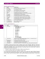
Table 5–22: HI-Z SPECIFIC DATA
#
NAME
DESCRIPTION
0
EadCounts
Total number of EAD counts for the phase
1
ArcConfidence
ArcConfidence for the phase
2
AccumArcConf
Accumulated ArcConfidence for the phase
3
RmsCurrent
The 2-cycle RMS current for the phase
4
HighROC
Flag indicating a high rate of change was detected
5
IOC
Flag indicating an instantaneous 2-cycle overcurrent was detected
6
LossOfLoad
Flag indicating a loss of load was detected
7
EadZeroed
Flag indicating that this phase’s EAD table was cleared
8
HighZArmed
Flag indicating that this phase is armed for a high-Z detection
9
VoltageDip
Flag indicating that a voltage dip was detected on this phase
10
HighEad
Flag indicating that a high arc confidence occurred on this phase
11
ArcBurst
Flag indicating that an arc burst was identified on this phase
12
VDisturbanceCc
Cycle-to-cycle voltage disturbance
13
VDisturbanceAbs
Absolute voltage disturbance
14
HarmonicRestraint
Harmonic Restraint
Table 5–23: HI-Z CAPTURE DATA
#
NAME
DESCRIPTION
1
StatusMask
Bit-mask of the algorithm state (16 bits)
BIT_ARCING
BIT_DOWNED_COND
BIT_ARC_TREND
BIT_PHASE_A
BIT_PHASE_B
BIT_PHASE_C
BIT_PHASE_N
BIT_IOC_A
BIT_IOC_B
BIT_IOC_C
BIT_IOC_N
BIT_LOL_A
BIT_LOL_B
BIT_LOL_C
BIT_I_DISTURBANCE
BIT_V_DISTURBANCE
2
AlgorithmState
Present value of the High-Z output state machine: Normal = 0, Coordination Timeout = 1,
Armed = 2, Arcing = 5, Downed Conductor = 9
3
EadZeroedFlag
Flag indicating the EAD table was cleared
4
SpectralFlag
Flag indicating the Spectral algorithm has found a match
5
ThreePhaseFlag
Flag indicating a three phase event was detected
6
PhaseInfo[4]
Phase specific information for the three phase currents and the neutral (see table below)
Summary of Contents for F60 UR Series
Page 2: ......
Page 4: ......
Page 30: ...1 20 F60 Feeder Protection System GE Multilin 1 5 USING THE RELAY 1 GETTING STARTED 1 ...
Page 48: ...2 18 F60 Feeder Protection System GE Multilin 2 2 SPECIFICATIONS 2 PRODUCT DESCRIPTION 2 ...
Page 126: ...4 30 F60 Feeder Protection System GE Multilin 4 2 FACEPLATE INTERFACE 4 HUMAN INTERFACES 4 ...
Page 354: ...5 228 F60 Feeder Protection System GE Multilin 5 9 TESTING 5 SETTINGS 5 ...
Page 382: ...6 28 F60 Feeder Protection System GE Multilin 6 5 PRODUCT INFORMATION 6 ACTUAL VALUES 6 ...
Page 398: ...8 8 F60 Feeder Protection System GE Multilin 8 2 FAULT LOCATOR 8 THEORY OF OPERATION 8 ...
Page 414: ...A 14 F60 Feeder Protection System GE Multilin A 1 PARAMETER LIST APPENDIXA A ...
Page 492: ...B 78 F60 Feeder Protection System GE Multilin B 4 MEMORY MAPPING APPENDIXB B ...
Page 530: ...D 10 F60 Feeder Protection System GE Multilin D 1 IEC 60870 5 104 APPENDIXD D ...
Page 542: ...E 12 F60 Feeder Protection System GE Multilin E 2 DNP POINT LISTS APPENDIXE E ...
Page 558: ...x F60 Feeder Protection System GE Multilin INDEX ...

