GE Multilin
F60 Feeder Protection System
5-201
5 SETTINGS
5.6 CONTROL ELEMENTS
5
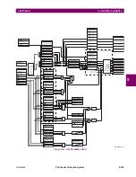
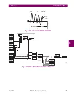
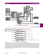
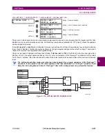
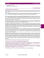
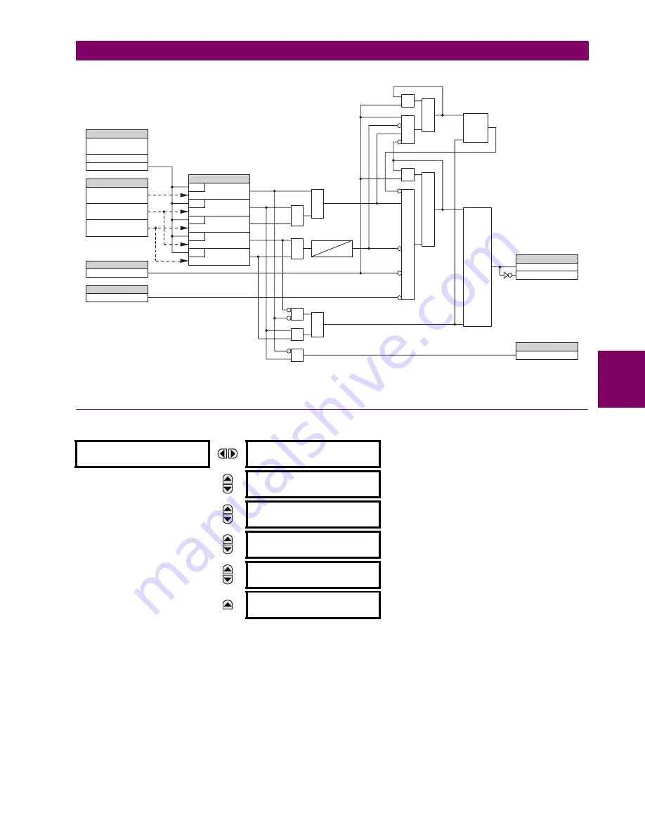
Figure 5–106: VT FUSE FAIL SCHEME LOGIC
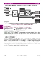
5.6.12 COLD LOAD PICKUP
PATH: SETTINGS
ÖØ
CONTROL ELEMENTS
ÖØ
COLD LOAD PICKUP
Ö
COLD LOAD PICKUP 1(2)
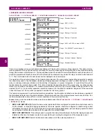
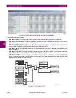
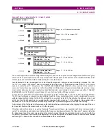
There are two (2) identical Cold Load Pickup features available, numbered 1 and 2.
This feature can be used to change protection element settings when (by changing to another settings group) a cold load
condition is expected to occur. A cold load condition can be caused by a prolonged outage of the load, by opening of the
circuit breaker, or by a loss of supply even if the breaker remains closed. Upon the return of the source, the circuit will expe-
rience inrush current into connected transformers, accelerating currents into motors, and simultaneous demand from many
other loads because the normal load diversity has been lost. During the cold load condition, the current level can be above
the pickup setting of some protection elements, so this feature can be used to prevent the tripping that would otherwise be
caused by the normal settings.
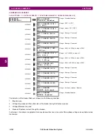
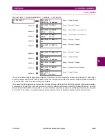
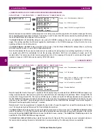
COLD LOAD PICKUP 1
COLD LOAD 1
FUNCTION: Disabled
Range: Disabled, Enabled
MESSAGE
COLD LOAD 1 PICKUP
SOURCE: SRC 1
Range: SRC 1, SRC 2
MESSAGE
COLD LOAD 1 INIT:
Off
Range: FlexLogic™ operand
MESSAGE
COLD LOAD 1 BLK:
Off
Range: FlexLogic™ operand
MESSAGE
OUTAGE TIME BEFORE
COLD LOAD1: 1000 s
Range: 0 to 1000 s in steps of 1
MESSAGE
ON-LOAD TIME BEFORE
RESET1: 100.000
Range: 0.000 to 1000 000.000 s in steps of 0.001
827093AK.CDR
VT FUSE FAILURE
FUNCTION:
V_2 > 0.1 p.u.
V_1 < 0.05 p.u.
V_1 < 0.7 p.u.
I_1 > 0.075 p.u.
I_1 < 0.05 p.u.
RUN
RUN
RUN
RUN
RUN
SETTING
COMPARATORS
SOURCE 1
FLEXLOGIC OPERANDS
FLEXLOGIC OPERAND
FLEXLOGIC OPERAND
FLEXLOGIC OPERAND
Disabled=0
Enabled=1
SRC1 VT FUSE FAIL OP
SRC1 VT FUSE FAIL VOL LOSS
SRC1 VT FUSE FAIL DPO
FUSE
FAIL
FAULT
SRC1 50DD OP
OPEN POLE OP
D60, L60, and L90 only
AND
AND
AND
AND
SET
RESET
Reset-dominant
LATCH
AND
AND
AND
AND
AND
OR
OR
OR
OR
V_1
I_1
V_2
20 CYCLES
2 CYCLES
LATCH
SET
Reset-dominant
RESET
Summary of Contents for F60 UR Series
Page 2: ......
Page 4: ......
Page 30: ...1 20 F60 Feeder Protection System GE Multilin 1 5 USING THE RELAY 1 GETTING STARTED 1 ...
Page 48: ...2 18 F60 Feeder Protection System GE Multilin 2 2 SPECIFICATIONS 2 PRODUCT DESCRIPTION 2 ...
Page 126: ...4 30 F60 Feeder Protection System GE Multilin 4 2 FACEPLATE INTERFACE 4 HUMAN INTERFACES 4 ...
Page 354: ...5 228 F60 Feeder Protection System GE Multilin 5 9 TESTING 5 SETTINGS 5 ...
Page 382: ...6 28 F60 Feeder Protection System GE Multilin 6 5 PRODUCT INFORMATION 6 ACTUAL VALUES 6 ...
Page 398: ...8 8 F60 Feeder Protection System GE Multilin 8 2 FAULT LOCATOR 8 THEORY OF OPERATION 8 ...
Page 414: ...A 14 F60 Feeder Protection System GE Multilin A 1 PARAMETER LIST APPENDIXA A ...
Page 492: ...B 78 F60 Feeder Protection System GE Multilin B 4 MEMORY MAPPING APPENDIXB B ...
Page 530: ...D 10 F60 Feeder Protection System GE Multilin D 1 IEC 60870 5 104 APPENDIXD D ...
Page 542: ...E 12 F60 Feeder Protection System GE Multilin E 2 DNP POINT LISTS APPENDIXE E ...
Page 558: ...x F60 Feeder Protection System GE Multilin INDEX ...

