GE Multilin
F60 Feeder Protection System
2-9
2 PRODUCT DESCRIPTION
2.2 SPECIFICATIONS
2
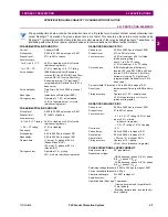
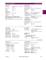
AUXILIARY OVERVOLTAGE
Pickup level:
0.000 to 3.000 pu in steps of 0.001
Dropout level:
97 to 98% of pickup
Level accuracy:
±0.5% of reading from 10 to 208 V
Pickup delay:
0 to 600.00 s in steps of 0.01
Reset delay:
0 to 600.00 s in steps of 0.01
Timing accuracy:
±3% of operate time or ±4 ms
(whichever is greater)
Operate time:
<
30 ms at 1.10
×
pickup at 60 Hz
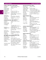
NEGATIVE SEQUENCE OVERVOLTAGE
Pickup level:
0.000 to 1.250 pu in steps of 0.001
Dropout level:
97 to 98% of pickup
Level accuracy:
±0.5% of reading from 10 to 208 V
Pickup delay:
0 to 600.00 s in steps of 0.01
Reset delay:
0 to 600.00 s in steps of 0.01
Time accuracy:
±3% or ±20 ms, whichever is greater
Operate time:
< 30 ms at 1.10
×
pickup at 60 Hz
UNDERFREQUENCY
Minimum signal:
0.10 to 1.25 pu in steps of 0.01
Pickup level:
20.00 to 65.00 Hz in steps of 0.01
Dropout level:
0.03 Hz
Level accuracy:
±0.001 Hz
Time delay:
0 to 65.535 s in steps of 0.001
Timer accuracy:
±3% or 4 ms, whichever is greater
Operate time:
typically 4 cycles at 0.1 Hz/s change
typically 3.5 cycles at 0.3 Hz/s change
typically 3 cycles at 0.5 Hz/s change
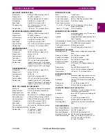
OVERFREQUENCY
Pickup level:
20.00 to 65.00 Hz in steps of 0.01
Dropout level:
pickup – 0.03 Hz
Level accuracy:
±0.001 Hz
Time delay:
0 to 65.535 s in steps of 0.001
Timer accuracy:
±3% or 4 ms, whichever is greater
Operate time:
typically 4 cycles at 0.1 Hz/s change
typically 3.5 cycles at 0.3 Hz/s change
typically 3 cycles at 0.5 Hz/s change
RATE OF CHANGE OF FREQUENCY
df/dt trend:
increasing, decreasing, bi-directional
df/dt pickup level:
0.10 to 15.00 Hz/s in steps of 0.01
df/dt dropout level:
96% of pickup
df/dt level accuracy:
80 mHz/s or 3.5%, whichever is greater
Overvoltage supv.:
0.100 to 3.000 pu in steps of 0.001
Overcurrent supv.:
0.000 to 30.000 pu in steps of 0.001
Pickup delay:
0 to 65.535 s in steps of 0.001
Reset delay:
0 to 65.535 s in steps of 0.001
Time accuracy:
±3% or ±4 ms, whichever is greater
95% settling time for df/dt: < 24 cycles
Operate time:
12 cycles at 2
×
pickup
8 cycles at 3
×
pickup
5 cycles at 5
×
pickup
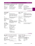
BREAKER FAILURE
Mode:
1-pole, 3-pole
Current supervision:
phase, neutral current
Current supv. pickup:
0.001 to 30.000 pu in steps of 0.001
Current supv. dropout:
97 to 98% of pickup
Current supv. accuracy:
0.1 to 2.0
×
CT rating: ±0.75% of reading or ±2% of rated
(whichever is greater)
above 2
×
CT rating:
±2.5% of reading
BREAKER ARCING CURRENT
Principle:
accumulates breaker duty (I
2
t) and mea-
sures fault duration
Initiation:
programmable per phase from any Flex-
Logic™ operand
Compensation for auxiliary relays: 0 to 65.535 s in steps of 0.001
Alarm threshold:
0 to 50000 kA2-cycle in steps of 1
Fault duration accuracy: 0.25 of a power cycle
Availability:
1 per CT bank with a minimum of 2
BREAKER FLASHOVER
Operating quantity:
phase current, voltage and voltage differ-
ence
Pickup level voltage:
0 to 1.500 pu in steps of 0.001
Dropout level voltage:
97 to 98% of pickup
Pickup level current:
0 to 1.500 pu in steps of 0.001
Dropout level current:
97 to 98% of pickup
Level accuracy:
±0.5% or ±0.1% of rated, whichever is
greater
Pickup delay:
0 to 65.535 s in steps of 0.001
Time accuracy:
±3% or ±42 ms, whichever is greater
Operate time:
<42 ms at 1.10
×
pickup at 60 Hz
BREAKER RESTRIKE
Principle:
detection of high-frequency overcurrent
condition ¼ cycle after breaker opens
Availability:
one per CT/VT module (not including 8Z
modules)
Pickup level:
0.1 to 2.00 pu in steps of 0.01
Reset delay:
0.000 to 65.535 s in steps of 0.001
INCIPIENT CABLE FAULT DETECTION
Principle:
detection of ½ cycle or less overcurrent
condition during normal load
Availability:
two per CT/VT module (not including 8Z
modules)
Pickup level:
0.1 to 10.00 pu in steps of 0.01
Reset delay:
0.000 to 65.535 s in steps of 0.001
Operating mode:
number of counts, counts per time win-
dow
SYNCHROCHECK
Max voltage difference:
0 to 400000 V in steps of 1
Max angle difference:
0 to 100
°
in steps of 1
Max freq. difference:
0.00 to 2.00 Hz in steps of 0.01
Hysteresis for max. freq. diff.: 0.00 to 0.10 Hz in steps of 0.01
Dead source function:
None, LV1 & DV2, DV1 & LV2, DV1 or
DV2, DV1 xor DV2, DV1 & DV2
(L = Live, D = Dead)
Summary of Contents for F60 UR Series
Page 2: ......
Page 4: ......
Page 30: ...1 20 F60 Feeder Protection System GE Multilin 1 5 USING THE RELAY 1 GETTING STARTED 1 ...
Page 48: ...2 18 F60 Feeder Protection System GE Multilin 2 2 SPECIFICATIONS 2 PRODUCT DESCRIPTION 2 ...
Page 126: ...4 30 F60 Feeder Protection System GE Multilin 4 2 FACEPLATE INTERFACE 4 HUMAN INTERFACES 4 ...
Page 354: ...5 228 F60 Feeder Protection System GE Multilin 5 9 TESTING 5 SETTINGS 5 ...
Page 382: ...6 28 F60 Feeder Protection System GE Multilin 6 5 PRODUCT INFORMATION 6 ACTUAL VALUES 6 ...
Page 398: ...8 8 F60 Feeder Protection System GE Multilin 8 2 FAULT LOCATOR 8 THEORY OF OPERATION 8 ...
Page 414: ...A 14 F60 Feeder Protection System GE Multilin A 1 PARAMETER LIST APPENDIXA A ...
Page 492: ...B 78 F60 Feeder Protection System GE Multilin B 4 MEMORY MAPPING APPENDIXB B ...
Page 530: ...D 10 F60 Feeder Protection System GE Multilin D 1 IEC 60870 5 104 APPENDIXD D ...
Page 542: ...E 12 F60 Feeder Protection System GE Multilin E 2 DNP POINT LISTS APPENDIXE E ...
Page 558: ...x F60 Feeder Protection System GE Multilin INDEX ...

