5-4
750/760 Feeder Management Relay
GE Multilin
5.1 OVERVIEW
5 SETPOINTS
5
5.1.2 SETPOINT ENTRY METHODS
Prior to operating the relay on a feeder, setpoints defining system characteristics, inputs, relay outputs, and protection set-
tings must be entered, via one of the following methods:
•
Front panel, using the keys and display.
•
Front program port, and a portable computer running the 750/760PC software supplied with the relay.
•
Rear RS485/RS422 COM1 port or RS485 COM2 port and a SCADA system running user-written software.
Any of these methods can be used to enter the same information. A computer, however, makes entry much easier. Files
can be stored and downloaded for fast, error free entry when a computer is used. To facilitate this process, a GE Multilin
Products CD with the 750/760PC software is supplied with the relay.
The relay leaves the factory with setpoints programmed to default values, and it is these values that are shown in all the
setpoint message illustrations. Many of these factory default values can be left unchanged.
At a minimum, the
S2 SYSTEM SETUP
setpoints must be entered for the system to function correctly. To safeguard
against the installation of a relay whose setpoints have not been entered, the relay
Relay Not Ready
self-test warn-
ing message is displayed. In addition, the Self-Test Warning Relay will be de-energized. Once the relay has been
programmed for the intended application, the
S1 RELAY SETUP
ÖØ
INSTALLATION
Ö
760 OPERATION
setpoint should
be changed from “Not Ready” (the factory default) to “Ready”.
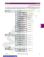
Some messages associated with disabled features are hidden. These context sensitive messages are illustrated with a dot-
ted border on the message box. Before putting the relay in the Ready state, each page of setpoint messages should be
worked through, entering values either by keypad or computer.
5.1.3 SETPOINT ACCESS SECURITY
Hardware and passcode security features are designed into the relay to provide protection against unauthorized setpoint
changes.
To program new setpoints using the front panel keys, a hardware jumper must be installed across the setpoint access ter-
minals on the back of the relay. These terminals can be permanently wired to a panel mounted key switch if desired.
Attempts to enter a new setpoint without the electrical connection across the setpoint access terminals will result in an error
message. The jumper does not restrict setpoint access via serial communications.
The relay has a programmable passcode setpoint which may be used to disallow setpoint changes from both the front
panel and the serial communications ports. This passcode consists of up to eight (8) alphanumeric characters.
The factory default passcode is “0”. When this specific value is programmed into the relay it has the effect of removing all
setpoint modification restrictions. Therefore, only the setpoint access jumper can be used to restrict setpoint access via the
front panel and there are no restrictions via the communications ports.
When the passcode is programmed to any other value, setpoint access is restricted for the front panel and all communica-
tions ports. Access is not permitted until the passcode is entered via the keypad or is programmed into a specific register
(via communications). Note that enabling setpoint access on one interface does not automatically enable access for any of
the other interfaces (i.e., the passcode must be explicitly set in the relay via the interface from which access is desired).
A front panel command can disable setpoint access once all modifications are complete. For the communications ports,
access is disabled by writing an invalid passcode into the register previously used to enable setpoint access. In addition,
setpoint access is automatically disabled on an interface if no activity is detected for thirty minutes.
The 750/760PC software incorporates a facility for programming the relay’s passcode as well as enabling/disabling setpoint
access. For example, when an attempt is made to modify a setpoint but access is restricted, the program will prompt the
user to enter the passcode and send it to the relay before the setpoint is actually written to the relay. If a SCADA system is
used for relay programming, it is up to the programmer to incorporate appropriate security for the application.
5.1.4 COMMON SETPOINTS
To make the application of this device as simple as possible, similar methods of operation and therefore similar types of
setpoints are incorporated in various features. Rather than repeat operation descriptions for this class of setpoint through-
out the manual, a general description is presented in this overview. Details that are specific to a particular feature will be
included in the discussion of the feature. The form and nature of these setpoints is described below.
W
A
R
NIN
G


