GE Multilin
750/760 Feeder Management Relay
3-5
3 INSTALLATION
3.1 MECHANICAL
3
3.1.4 REAR TERMINAL LAYOUT
Due to the many features built into the 750/760 relays, a broad range of applications are available to the user. As such, it is
not possible to present typical connections for all possible schemes. The information in this section will cover the important
aspects of interconnections, in the general areas of instrument transformer inputs, other inputs, outputs, communications
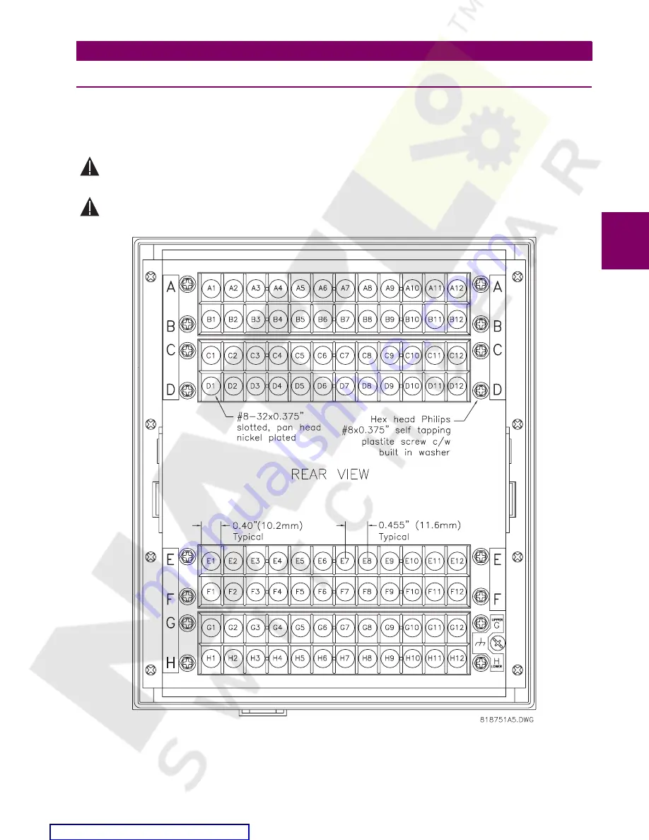
and grounding. The figure below shows the rear terminal layout of the 750/760.
Relay contacts must be considered unsafe to touch when system is energized! If the customer requires the
relay contacts for low voltage accessible applications, it is their responsibility to ensure proper insulation
levels!
HAZARD may result if the product is not used for its intended purposes.
Figure 3–8: REAR TERMINAL LAYOUT
W
A
R
NIN
G
W
A
R
NIN
G


