background image


Modifications reserved 

Page 27/90 

GE_UPS_USM_TLE_SUL_40K_M15_1US_V010.docx 

User Manual

 TLE Scalable Series 40 - 150 UL S1


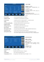
LEDs on Synoptic Diagram 

LED 1  Rectifier 
LED 2


Inverter 

LED 3  Booster/Battery charger 
LED 4  Automatic Bypass 
LED 5  LOAD 


Examples of typical scenarios in the Synoptic Diagram: 


Load supplied by Inverter 

Load supplied by Automatic Bypass 


SEM Operation Mode


Load supplied by Battery


IEMi Operation Mode, unit on-line 

IEMi Operation Mode, unit stand-by 


Summary of Contents for FGC TLE Series

Page 1: ...TLE SERIES UPS 40 150 KVA KW 480 VAC Three phase Highly Efficient and Scalable GE Industrial Solutions...

Page 2: ...onitors the output voltage and frequency and will instantaneously switch to double conversion mode and inverter usage during voltage and or frequency disturbances to insure compliance with the ITI CBE...

Page 3: ...bolt on battery monitoring systems Optional maintenance bypass capabilities via external wrap around cabinetry Optional 208VAC output via matching stepdown transformer cabinetry Optional output distri...

Page 4: ...ries UPS is equipped with menu driven touch screen display panel provides easy to read details on UPS status and metering parameter settings UPS configuration This user friendly display panel provides...

Page 5: ...isfeature reducesthe need ofoversizingthe input power system gensets feedercables and overcurrent devices Generator Compatibility User programmable features such as slew rate phase angle rate of chang...

Page 6: ...reased load capacity or redundancy Scalable The system can be easily expanded for higher capacity and redundancy without any interruption to the critical load ortransferto bypass Distributed Control L...

Page 7: ...UPS performance is optimized at 50 75 load operation as this is the most common operating range The optimization of theTLE Series includes selecting all major power chain components based on maximizin...

Page 8: ...Black Service access Front and top access only External cable connections Bottom at the front of the cabinet or top with lateral sidecar Paralleling RPA version Up to 6 units for redundancy or capaci...

Page 9: ...49 lbs 385 Kg 992 lbs 450 Kg 1147 lbs 520 Kg Floor loading 152 lbs sq ft 742 Kg m2 178 lbs sq ft 867 Kg m2 205 lbs sq ft 1002 Kg m2 Dimensions WxDxH 23 62 x 34 06 x 64 17 inches 600 x 865 x 1630 mm BY...

Page 10: ...29 40 1 40 0 40 0 29 5 75 0 3 220 lbs 3 220 lbs 38 40 1 40 0 40 0 29 5 75 0 3 500 lbs 3 500 lbs 54 40 1 40 0 40 0 29 5 75 0 4 620 lbs 4 620 lbs 58 80 2 40 0 40 0 29 5 75 0 2 860 lbs 5 720 lbs 77 80 2...

Page 11: ...bs 13 860 lbs 150Kva 150Kw 5 40 1 40 0 40 0 29 5 75 0 3 500 lbs 3 500 lbs 9 40 1 40 0 40 0 29 5 75 0 4 620 lbs 4 620 lbs 12 80 2 40 0 80 0 29 5 75 0 2 860 lbs 5 720 lbs 17 80 2 40 0 80 0 29 5 75 0 3 2...

Page 12: ...data transmission SSL encrypted with unidirectional communication iUPSGuard can communicate through various channels and monitors single UPS or parallel UPS systems through web SNMP card Detailed repo...

Page 13: ...and startup to availability services to help you proactively reduce downtime and meet your service level commitments From installationto product retirement warranty upgradesto remote monitoring proac...

Page 14: ...14 LP33 Series II UPS www gecriticalpower com Notes...

Page 15: ...15 LP33 Series II UPS www gecriticalpower com Notes...

Page 16: ...of the General Electric Company The GE brand logo and lumination are trademarks of the General Electric Company 2017 General Electric Company Information provided is subject to change without notice...

Page 17: ...Uninterruptible Power Supply GE Consumer Industrial SA General Electric Company CH 6595 Riazzino Locarno Switzerland T 41 0 91 850 51 51 F 41 0 91 850 52 52 www gecriticalpower com imagination at wor...

Page 18: ...2 2017 File name GE_UPS_ISG_TLE_SUL_40K_M15_1US_V010 Revision 1 0 Identification No 8600123208P Up dating Revision Concern Date COPYRIGHT 2017 by GE Consumer Industrial SA All rights reserved The info...

Page 19: ...bout the installation of the UPS Thank you for choosing GE START UP AND COMMISSIONING A GE GLOBAL SERVICES FIELD ENGINEER must perform start up and commissioning of the UPS Please Contact GE GLOBAL SE...

Page 20: ...ing from the use of the information contained in this document WARNING TLE Scalable Series 40 150 is a product that needs to be installed by a licensed and knowledgeable contractor Installation restri...

Page 21: ...s 40 150 Power connection with Common Input Utility 31 4 8 2 TLE Scalable Series 40 150 Power connection with Dual Input Utility 33 4 8 3 Battery cabinet connection to TLE Scalable Series 40 150 35 4...

Page 22: ...y accurately during Commissioning and Maintenance of the UPS for the following Damaged components squeezed wires and cables or not correctly inserted plugs After removing the sidewalls of the UPS make...

Page 23: ...tool to short between individual or separate battery terminals or to the cabinet or rack Do not lay tools or metal parts on top of the battery and do not lay them where they could fall onto the batte...

Page 24: ...this manual the following symbols are defined WARNING if instruction is not followed injury or serious equipment damage may occur CAUTION internal parts have dangerous voltage present Risk of electri...

Page 25: ...2 LAYOUT 2 1 LAYOUT TLE SCALABLE Series 40 150 Fig 2 1 1 TLE Scalable Series 40 150 General view Fig 2 1 2 Control panel Fig 2 1 3 Q1 UPS Output switch Fig 2 1 4 Connectivity Slots TLES_040 120_S1_UPS...

Page 26: ...nection CI Customer Interface Board see Fig 2 1 4 CR Connectivity Slots J35 P Serial port RS232 for IMV protocol Q1 UPS Output switch RPA RPA board Redundant Parallel Architecture for Parallel System...

Page 27: ...lorid PACKING MATERIAL RECYCLING GE in compliance with environment protection uses only environmentally friendly material UPS packing materials must be recycled in compliance with all applicable regul...

Page 28: ...the unpacked UPS Forklift The UPS may be lifted with a forklift in upright position Take note of the center of gravity marked on the package Crane Fig 4 1 2 Position of the carrying belts when moving...

Page 29: ...ns W x D x H Standard UPS 23 62 x 34 06 x 64 17 inches 600 x 865 x 1630 mm UPS with options TCE THF 27 56 x 34 06 x 75 00 inches 700 x 865 x 1905 mm Weight Standard UPS 992 lbs 450 kg UPS with options...

Page 30: ...0 inches 757 x 750 x 1905 mm 40 00 x 29 50 x 75 00 inches 1016 x 750 x 1905 mm Lbs kg lbs sq ft kg m2 TLE Scalable Series 150 50 TLE Scalable Series 150 80 TLE Scalable Series 150 100 TLE Scalable Ser...

Page 31: ...ances and with a temperature range not exceeding 13 F 25 C to 131 F 55 C In case the battery is included please refer to Section 4 3 2 Some important functions of the UPS such as the customized functi...

Page 32: ...ance free Operation at temperatures higher than 77 F 25 C will reduce battery life The TLE Scalable Series 40 150 UPS can radiate radio frequency energy Although some RFI Radio Frequency Interference...

Page 33: ...g of the UPS cabinet TLE Scalable Series 40 150 on the floor The UPS cabinet is free standing and normally does not require to be bolted to the floor The UPS cabinet can be fixed however to the floor...

Page 34: ...nge 4 F 20 C to 104 F 40 C The life of valve regulated batteries will be reduced by 50 for each additional 18 F 10 C that the battery ambient temperature is above 77 F 25 C The Battery System associat...

Page 35: ...tude for cooling air 77 F 25 C to 86 F 30 C UPS model Losses Cooling air flow VFI SEM Super Eco Mode VFI PF 0 9 PF 1 PF 0 9 PF 1 PF 0 9 PF 1 TLE Scalable Series 150 40 6005 BTU hr 1760 kW 6142 BTU hr...

Page 36: ...GE Service Center Fig 4 6 1 ShockWatch device Fig 4 6 2 TiltWatch device NOTE Be aware of the heavy weight of the UPS pay attention when moving the UPS cabinet Take care not to damage the UPS when mov...

Page 37: ...etch foil check the status of the A Humidity indicator 10 to 70 The UPS can be commissioned 80 The UPS shall not be commissioned Please contact your GE Service Center Fig 4 6 4 Location of the Protect...

Page 38: ...d from a Common Input source or Dual Input sources if desired Common Input Utility Rectifier Bypass Fig 4 7 1 1 Common Input Utility Rectifier Bypass The same power source is to be used for both Bypas...

Page 39: ...connected and grounded solidly due to the existence of voltage surge protection devices inside the UPS The connection of the Battery to the UPS must be protected with fuses or similar devices accordi...

Page 40: ...requirement is based on the current data below The maximum available fault current from the battery supply is 20kA The minimum breaker voltage rating is 540V Fig 4 7 3 1 Common Input Rectifier Bypass...

Page 41: ...120 225 A 200 A 225 A 300 A TLE Scalable Series 150 150 300 A 250 A 300 A 400 A WIRING Wire sizing according to NEC Section 210 20 A Table 310 16 Use 194 F 90 C copper Wiring requirements AC INPUT REC...

Page 42: ...45 6 55 65 75 40 50 60 4 70 85 95 55 65 75 3 85 100 110 65 75 85 2 95 115 130 75 90 100 1 110 130 150 85 100 115 1 0 125 150 170 100 120 135 2 0 145 175 195 115 135 150 3 0 165 200 225 130 155 175 4...

Page 43: ...e Series 40 150 Single UPS with Common Input Utility for Rectifier Bypass Single UPS with Common Input Utility for Rectifier Bypass 3 wire distribution 3 phase plus ground Single UPS with Dual Input U...

Page 44: ...S_ISG_TLE_SUL_40K_M15_1US_V010 docx Installation Guide TLE Scalable Series 40 150 UL S1 UPS Parallel System with Common Input Utility Rectifier Bypass UPS Parallel System with Common Input Utility Rec...

Page 45: ...TLE Scalable Series 40 150 UL S1 UPS Parallel System with Dual Input Utility for Rectifier Bypass Connect a single input Neutral to Bypass Utility inside the UPS common Neutral for Bypass and Rectifi...

Page 46: ...to avoid risk of short circuit between different poles The grounding and neutral connection of the electrical system must be in accordance with local regulations In case of additional cabinets contain...

Page 47: ...C L3 PE Ground Input Utility NOTE The interconnection links BR1 BR2 and BR3 on the input bus bars MUST REMAIN CONNECTED see Fig 4 8 1 1 Output Load L1 Load phase A L1 L2 Load phase B L2 L3 Load phase...

Page 48: ...ain a Neutral Bus as per the following Figure 4 8 1 2 If no Neutral Connection is available with the Bypass Input 3 wire input ground and the Load does not require a Neutral solidly connect the Output...

Page 49: ...pass phase C L3 PE Ground Input Utility N Neutral Input Utility NOTE The interconnection links BR1 BR2 and BR3 on the input bus bars MUST BE REMOVED see Fig 4 8 2 3 Output Load L1 Load phase A L1 L2 L...

Page 50: ...ain a Neutral Bus as per the following Figure 4 8 2 2 If no Neutral Connection is available with the Bypass Input 3 wire input ground and the Load does not require a Neutral solidly connect the Output...

Page 51: ...4B75 C rating size per NEC Table 310 16 and or all applicable national and local codes see also Section 4 7 4 Battery cabinet can be located on either side of the UPS The connecting cables PE are supp...

Page 52: ...mperature sensor TLES_UL_040 150_S1_UPS IM0284 J14_01US EPO EPO XA Q1 I ON 0 OFF J35 J36 TP5 TP4 C34 C35 C64 C63 C56 C54 L2 L1 J31 J37 J34 J38 C62 C61 R102 R101 R100 R99 R98 R38 R86 R76 R66 R56 R46 R1...

Page 53: ...input characteristic As the inverter output filter exhibits a predominantly capacitive characteristic it may provide some degree of reactive power compensation when combined with lagging power factor...

Page 54: ...ency converter the SEM Operation Mode is automatically disabled Fig 4 8 5 1 Interconnection links BR1 BR2 and BR3 In order to avoid improper operation only the Rectifier input should be powered L1 1 L...

Page 55: ...the same for all units of the Parallel System no phase shift allowed between units NOTE It is strongly recommended that no transformers automatic circuit breakers or fuses should be inserted between...

Page 56: ...bles In this way communication is maintained between units in case one of the control cables should fail or be accidentally damaged or disconnected The standard length of the control bus cable between...

Page 57: ...s of a Parallel System the switches SW1 1 2 3 4 5 6 MUST BE IN POSITION ON see Fig 4 9 2 2 Fig 4 9 2 3 Bus connection on intermediate units Intermediate units of a RPA Parallel System On the two board...

Page 58: ...onnection The communication bus cable connectors are placed on the two boards P13 P14 IM0022 Bus Interface Board see Fig 4 9 3 1 Fig 4 9 3 2 View electronic module on intermediate unit Control bus cab...

Page 59: ...ONNECTING THEM from the two boards P13 P14 IM0022 Bus Interface Board For reliability reasons the cables J1A J2A 1 2 3 4 5 and J1B J2B 1 2 3 4 5 connecting the units should be run in separated protect...

Page 60: ...ic Switch NOTE This procedure could imply a Load shut down Keep SELV cables separated from HIGH VOLTAGE cables Fig 4 10 2 XA EPO Emergency Power Off RPA Parallel System connection schematics In a Para...

Page 61: ...System max 6 UPS it s possible to install the following connectivity boards max 3 Customer Interface boards for each UPS max 2 3 ph SNMP WEB Plug in Adapter boards for Parallel System ATTENTION The i...

Page 62: ...tware GE iUPSGuard GE Data Protection or GE Service Software for system protection and management of the UPS systems Fig 5 1 2 Serial port J35 P connection to PC with RS232 1 1 cable DB9m DB9f Connect...

Page 63: ...s On terminals X1 6 of the following 27 signals can be selected from the display entering with the appropriate password Some UPS functions can be activated with parameters when an external Normally Op...

Page 64: ...N def Parameter RL 5 X1 12 13 14 NO C NC LOAD ON MAINS def Parameter RL 2 X1 15 16 17 NO C NC GENERAL ALARM def Parameter RL 4 X1 18 19 20 NO C NC BUZZER ACOUSTIC ALARM def Parameter RL 6 In case diff...

Page 65: ...aux contact from the External Bypass Switch to the programmable input X1 10 21 making the UPS operate as if the internal switch Q2 has closed This function can be activated by changing a dedicated pa...

Page 66: ...provides UPS information via the standard SNMP Protocol UPS MIB RFC 1628 GE Single MIB GE Parallel MIB The UPS can therefore be monitored by a Network Management System NMS or by our applications for...

Page 67: ...on of input and output cables from the top of the UPS The Top Cable Entry Exit Sidecar can be located on either side of the UPS cabinet The Top Cable Entry Exit Sidecar is accessibly from right side s...

Page 68: ...etallic windows D from the metal screen Fix the structure E with the appropriate screws Fix the roof A of the UPS cabinet Fix the top plate F with the appropriate screws 1247BKnock out appropriate hol...

Page 69: ...ocx Installation Guide TLE Scalable Series 40 150 UL S1 7 NOTES 7 1 NOTES FORM It is recommended to note in this section Notes with date and short description all the operations performed on the UPS a...

Page 70: ...t Uninterruptible Power Supply GE Consumer Industrial SA General Electric Company CH 6595 Riazzino Locarno Switzerland T 41 0 91 850 51 51 F 41 0 91 850 52 52 www gecriticalpower com imagination at wo...

Page 71: ...sue 10 27 2017 File name GE_UPS_TDS_TLE_SUL_40K_M15_1US_V010 Revision 1 0 Identification No Up dating Revision Concern Date COPYRIGHT 2017 by GE Consumer Industrial SA All rights reserved The informat...

Page 72: ...e Internal protection All internal live parts shrouded Transport On pallet Cabinet suitable for handling by forklift Color RAL 9005 black Installation Minimum distance from the wall 2 5 cm and floor f...

Page 73: ...HD for 100 non linear load EN 62040 5 Output voltage tolerance at 100 unbalanced load Ph N 3 Output frequency 60 Hz Output frequency tolerance free running 0 1 with mains synchronization adjustable to...

Page 74: ...and Dutch Graphic diagram indicating UPS status Command keys and parameters setting UPS status control LED OPTIONS COMMUNICATION OPTIONS 1 Additional Customer Interface Card 2 iUPS Guard 3 GE Data Pr...

Page 75: ...ranch Circuit Over Current Protection All Models CAUTION To reduce the risk of fire only connect UPS to a circuit provided with see below maximum amperes branch circuit over current protection in acco...

Page 76: ...lbs 2096 kg 31 80 2 2860 lbs 1297 kg 5720 lbs 2594 kg 41 3220 lbs 1461 kg 6440 lbs 2922 kg 50 3500 lbs 1588 kg 7000 lbs 3176 kg 73 4620 lbs 2096 kg 9240 lbs 4192 kg 100 6 40 1 2860 lbs 1297 kg 2860 l...

Page 77: ...nterruptible Power Supply GE Consumer Industrial SA General Electric Company CH 6595 Riazzino Locarno Switzerland T 41 0 91 850 51 51 F 41 0 91 850 52 52 www gecriticalpower com imagination at work TL...

Page 78: ...017 File name GE_UPS_USM_TLE_SUL_40K_M15_1US_V010 Revision 1 0 Identification No 8600123209P Up dating Revision Concern Date COPYRIGHT 2017 by GE Consumer Industrial SA All rights reserved The informa...

Page 79: ...ut the use of the UPS Thank you for choosing GE START UP AND COMMISSIONING A GE GLOBAL SERVICES FIELD ENGINEER must perform start up and commissioning of the UPS Please Contact GE GLOBAL SERVICES at l...

Page 80: ...rom the use of the information contained in this document WARNING TLE Scalable Series 40 150 is a product that needs to be installed by a licensed and knowledgeable contractor Installation restriction...

Page 81: ...rt up of the TLE Scalable Series 40 150 55 7 1 2 Complete UPS shut down 59 7 1 3 Restore to normal operation after System shutdown with Load not supplied 60 7 1 4 Restore to normal operation after EPO...

Page 82: ...curately during Commissioning and Maintenance of the UPS for the following Damaged components squeezed wires and cables or not correctly inserted plugs After removing the sidewalls of the UPS make sur...

Page 83: ...ol to short between individual or separate battery terminals or to the cabinet or rack Do not lay tools or metal parts on top of the battery and do not lay them where they could fall onto the battery...

Page 84: ...is manual the following symbols are defined WARNING if instruction is not followed injury or serious equipment damage may occur CAUTION internal parts have dangerous voltage present Risk of electric s...

Page 85: ...l view with open door Fig 2 1 6 TLE Scalable Series 80 100 General view with open door Fig 2 1 7 TLE Scalable Series 120 150 General view with open door TLES_040 120_S1_UPS_GE_02 TLES_UL_040 150_S1_Sw...

Page 86: ...other UPS available allowing you to support a greater number of today s enterprise computing Power Factor Corrected PFC equipment High Efficiency Thanks to type Advanced Neutral Point Clamped three le...

Page 87: ...s eliminating all single points of failure The decentralized bypass offers great exibility to up or down grade the system in case future needs might change TLE Scalable Series 40 150 BEST IN CLASS EFF...

Page 88: ...s to modulation strategy applied to IGBT Bridge the rectifier provides clean input power in terms of low THDi and unity power factor Inverter The Inverter converts the DC voltage into a three phase AC...

Page 89: ...r is available the Load is normally powered through the Automatic Bypass When the Utility Voltage is detected out of the prescribed tolerances the Load is automatically transferred to the Inverter Whe...

Page 90: ...hen a Battery low warning occurs on a unit not necessary to support the present Load this unit will shut down after a timeout period selectable The Load is shared between the other units As the warnin...

Page 91: ...dition is corrected the Load will be automatically transferred back to the Inverter Fig 4 2 5 1 Block diagram Automatic Bypass If the UPS is unable to return to normal mode following an automatic tran...

Page 92: ...control circuitry see Fig 4 3 1 1 Parallel units for power capacity Several units can be paralleled in order to achieve output power greater than the maximum power of a single unit The maximum total...

Page 93: ...nicates with all other modules in order to act or react if necessary adapting to the new conditions 4 3 4 Synchronization All units are identical but one unit is arbitrarily selected as the reference...

Page 94: ...required to maintain a reliable supply to the critical load Then an efficiency optimization algorithm determines the best UPS configuration in order to maintain the running UPS in their highest effic...

Page 95: ...pared in advance before the installation The installation must be performed only with the UPS system completely shut down The AC Rectifiers input power 4 must be the same with clockwise phase rotation...

Page 96: ...fication label 4 6 WARRANTY GE operating through its authorized agents warrants that the standard products will be free of defects in materials and workmanship for a period as per contract specificati...

Page 97: ...RIAL RECYCLING GE in compliance with environment protection uses only environmentally friendly material UPS packing materials must be recycled in compliance with all applicable regulations RECYCLING A...

Page 98: ...l Panel positioned on the UPS front door acts as the UPS user interface Main features LCD Touch screen color graphic display See Chapter 6 Multilanguage communication interface English German Italian...

Page 99: ...e programmed to meet customer needs by changing parameters Operation commands of the UPS 6 1 HOME SCREEN Fig 6 1 1 LCD screen The LCD screen after 5 minutes of inactivity shuts down the backlight To r...

Page 100: ...6 2 EVENTS Shows in chronological order all the events occurred alarms messages commands handling etc See Section 6 3 SETUP Allows the user to customize some UPS functions to specific requirements and...

Page 101: ...ervice Key yellow color Key for disabling the Service Key procedure Used only by the Service Center LEDS UPS STATUS LED LOAD PROTECTED green color When lit indicates that the UPS is functioning correc...

Page 102: ...en LED STOP OPERATION red color It warns about the imminent Inverter stop default parameter 3 min and the consequent Load shut down as result of The battery is fully discharged and the Load cannot be...

Page 103: ...ptic Diagram LED 1 Rectifier LED 2 Inverter LED 3 Booster Battery charger LED 4 Automatic Bypass LED 5 LOAD Examples of typical scenarios in the Synoptic Diagram Load supplied by Inverter Load supplie...

Page 104: ...rs like AC DC and various statistics In this mode the keys perform the following functions Return to HOME screen Shows the main screen EVENTS See Section 6 3 Shows the main screen SETUP See Section 6...

Page 105: ...t shows the true battery autonomy Charge level The battery charge level On battery time Total operating time of the UPS on battery in hours BATTERY DISCHARGE COUNTER Residual Charge Level The number o...

Page 106: ...tolerance faults Number of fast transients The number of fast transients occurred on the bypass utility on the last seven days Bypass quality index The statistic evaluation in 100 good 0 bad of the B...

Page 107: ...ent power Total apparent Load power kVA UPS operation time Total operating time for the UPS in hours Active Power Total effective Load power kW SEM operation time Total operating time for the UPS in S...

Page 108: ...keys perform the following functions Shows the main screen MEASURES See Section 6 2 Return to HOME screen Shows the main screen SETUP See Section 6 4 Shows the main screen COMMANDS See Section 6 5 Sho...

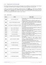
Page 109: ...n event Nr 511 is the more recent Nr 1 is the first Data MM DD YYYY Exact hour of the moment when the event occurred HH MM SS thousandth Number of standard GE code of the event Explicit text describin...

Page 110: ...FAILURE The parallel communication bus system is subject to high errors rate on channel JA 4007 BUS JB CRC FAILURE The parallel communication bus system is subject to high errors rate on channel JB 4...

Page 111: ...E Dangerous high DC Voltage caused Inverter shut down Inverter restarts automatically after Battery returns to floating voltage 4117 BATTERY EARTH FAULT A leakage current to earth has been detected on...

Page 112: ...FORMER OVERTEMPERATURE The temperature sensor of the Inverter Transformer indicates overtemperature Elapsed stop operation time Inverter shut down With Utility OK Load is transferred on Utility 4308 D...

Page 113: ...d remains supplied by Utility until the alarm stays ON 4522 FAN FAILURE The Fan Control Board indicates a malfunction of one or more ventilators 4530 LOAD LOCKED ON UTILITY Load is locked on Utility b...

Page 114: ...ard in particular from the DC supply Can be enabled or disabled with respective parameter 4702 LOSS OF REDUNDANCY A time of lost redundancy superior than specified in respective parameter was detected...

Page 115: ...settings 4124 MANUAL AUTOMATIC BOOST CHARGE STOP The automatic boost charge has finished The battery s voltage will return to the maintenance value A manually activated boost charge will finish if it...

Page 116: ...561 LOAD OFF Push button Load Off on the UPS Control Panel has been pressed with the output circuit switch Q1 closed 4562 DETOUR ON The auxiliary contact indicates that Q2 Manual Bypass was closed 456...

Page 117: ...de will be temporarily inhibited 4609 SEM INHIBITED LOW LOAD SEM Operation Mode inhibited due to minimal load not reached 4699 BATTERY TEST IMPOSSIBLE Automatic Battery Test is not possible due to No...

Page 118: ...without password protection In this mode the keys perform the following functions Shows the main screen MEASURES See Section 6 2 Shows the main screen EVENTS See Section 6 3 Return to HOME screen Sho...

Page 119: ...s are XON standing for the XON XOFF protocol or None standing for any protocol PRINTER COMMANDS By using the keys MEASURES ALARMS PARAMETERS ALL it is possible to print selected data NOTE Please confi...

Page 120: ...ing in VFI double conversion mode at all times When the UPS is in SEM Operating Mode the SEM LED is ON green light NOTE The configuration of the activation schedule can only be updated when SEM Operat...

Page 121: ...value NOTE To avoid undesired SEM Operation Mode verify Date and Time SEM screen how many hours of SEM Operation Mode have been selected for each day of the week NOTE The SEM Operation Mode will beco...

Page 122: ...f all Inverters in the system at least 1 minute of normal operation must be programmed during the week the Yes No parameter is automatically disabled if this condition is not satisfied In case this mi...

Page 123: ...many hours of IEMi Operation Mode have been selected for each day of the week NOTE For IEMi Operation Mode to become active a manual Inverter start is required at start up and after a Load Off reset T...

Page 124: ...e user to execute UPS operation commands In this mode the keys perform the following functions Shows the main screen MEASURES See Section 6 2 Shows the main screen EVENTS See Section 6 3 Shows the mai...

Page 125: ...ching ON command NOTE When SEM Operation Mode or IEMi Operation Mode is enabled control of Inverter status and selection of the feed path is done autonomously by the UPS control logic Therefore Invert...

Page 126: ...Shows the Module shutdown status ACTIVE NOT ACTIVE System shutdown System shutdown Load Off command for an RPA Parallel System NOTE This command will immediately disconnect the Load System shutdown c...

Page 127: ...EST Acoustical alarm test acoustical alarm should be always activated Module shutdown procedure Guides throught the procedures to shutdown a single UPS or a RPA Parallel System unit Attention For a si...

Page 128: ...nformation on the RPA Parallel System In this mode the keys perform the following functions Shows the main screen MEASURES See Section 6 2 NOTE During IEMi Operation Mode the Percent Load information...

Page 129: ...the RPA System Parallel Input Utility status for RECT Rectifier and BYP Bypass Battery status for CHRG Battery Charger green color On grey color Off Q1 Load output switch Q2 Manual Bypass switch only...

Page 130: ...structions given below However we recommend that at least the initial procedure should be performed by an instructed person Check after every step for correct reaction of the UPS LEDs on the panel and...

Page 131: ...ty screens are fixed in their position The switches Q1 is open Pos O and the Battery Cabinet Breaker must be open Pos O LEDs on Synoptic Diagram Q1 UPS Output switch LED 1 Rectifier LED 2 Inverter LED...

Page 132: ...and reliability of the UPS UPS Language This parameter allows the choice of language used to display the information Date dd mm yyyy You can adjust the date of the real time clock existing in the UPS...

Page 133: ...1 41Vdc for cell 284 309 cells x 1 41Vdc 401 436Vdc NiCd Battery with boost charge 1 41 1 55 boost charge Vdc for cell 281 cells x 1 41Vdc 397 436 Vdc Flooded Lead Acid Battery without boost charge 2...

Page 134: ...ker Pos I NOTE Before performing the next procedure 4 make sure that the LED 3 Booster Battery charger is lit 4 Insert the Inverter performing the command Inverter ON Perform the Inverter ON command f...

Page 135: ...ected from UPS Rectifier and Inverter are shut down and all contactors are opened LED 1 Rectifier and LED 2 Inverter are OFF LED ALARM is lit 2 Open Q1 UPS Output switch Pos O 3 Disconnect the battery...

Page 136: ...tput switch MUST BE CLOSED Pos I Battery Cabinet Breaker MUST BE OPEN Pos O Make sure that SEM Operation Mode is disabled before starting this procedure View of the Synoptic Diagram after performed th...

Page 137: ...NOTE Before performing the next procedure 3 make sure that the LED 3 Booster Battery charger is lit 3 Insert the Inverter performing the command Inverter ON Perform the Inverter ON command from the s...

Page 138: ...binet Breaker MUST BE OPEN Pos O Make sure that SEM Operation Mode is disabled before starting this procedure View of the Synoptic Diagram after performed the command EPO Emergency Power Off with LOAD...

Page 139: ...NOTE Before performing the next procedure 4 make sure that the LED 3 Booster Battery charger is lit 4 Insert the Inverter performing the command Inverter ON Perform the Inverter ON command from the s...

Page 140: ...pen Open the front door and make sure that All the connections to the input output terminals or bus bars of the UPS have been made correctly The safety screens are fixed in their position The switches...

Page 141: ...and reliability of the UPS UPS Language This parameter allows the choice of language used to display the information Date dd mm yyyy You can adjust the date of the real time clock existing in the UPS...

Page 142: ...1 41Vdc for cell 284 309 cells x 1 41Vdc 401 436Vdc NiCd Battery with boost charge 1 41 1 55 boost charge Vdc for cell 281 cells x 1 41Vdc 397 436 Vdc Flooded Lead Acid Battery without boost charge 2...

Page 143: ...polarities on both side of the switch fuse holder 3 Connect the battery to the UPS by closing the Battery Cabinet Breaker Pos I 4 Insert the Inverter performing the command Inverter ON Before performi...

Page 144: ...PS Rectifier and Inverter are shut down and all contactors are opened LED 1 Rectifier and LED 2 Inverter are OFF LED ALARM is lit 2 Open Q1 UPS Output switch Pos O 3 Disconnect the battery from the UP...

Page 145: ...Q1 UPS Output switch MUST BE CLOSED Pos I Battery Cabinet Breaker MUST BE OPEN Pos O View of the Synoptic Diagram after performed the command System shutdown with LOAD NOT SUPPLIED 1 Restore the comma...

Page 146: ...command Inverter ON Perform the Inverter ON command from the screen Commands 1 Inverter ON Soft start of Inverter indicated with blinking LED 2 Inverter At the end of Soft start the LED 2 Inverter re...

Page 147: ...make sure that the UPS is in the following status Q1 UPS Output switch MUST BE CLOSED Pos I Battery Cabinet Breaker MUST BE OPEN Pos O View of the Synoptic Diagram after performed the command EPO Eme...

Page 148: ...ng the Battery Cabinet Breaker Pos I NOTE Before performing the next procedure 4 make sure that the LED 3 Booster Battery charger is lit 4 Insert the Inverter performing the command Inverter ON Perfor...

Page 149: ...ixed in their position The switches Q1 is open Pos O and the Battery Cabinet Breaker must be open Pos O LEDs on Synoptic Diagram Q1 UPS Output switch LED 1 Rectifier LED 2 Inverter LED 3 Booster Batte...

Page 150: ...and reliability of the UPS UPS Language This parameter allows the choice of language used to display the information Date dd mm yyyy You can adjust the date of the real time clock existing in the UPS...

Page 151: ...1 41Vdc for cell 284 309 cells x 1 41Vdc 401 436Vdc NiCd Battery with boost charge 1 41 1 55 boost charge Vdc for cell 281 cells x 1 41Vdc 397 436 Vdc Flooded Lead Acid Battery without boost charge 2...

Page 152: ...indicates that the DC link 1 and DC link 2 has reached 400Vdc see screen MEASURES Rectifier Attention check the right DC polarities on both side of the switch fuse holder 3 Connect the Battery on all...

Page 153: ...sfer to Inverter LED ALARM turns Off and the LED LOAD PROTECTED must be lit The Synoptic Diagram on all UPS units must display the status LOAD SUPPLIED BY INVERTER Synoptic Diagram of first unit Synop...

Page 154: ...m all Inverters of the Redundant Parallel System 1 Disconnect the Inverter performing the Inverter OFF command on the Unit to separate 1 Perform the Inverter OFF command from the screen Commands 1 Inv...

Page 155: ...Pos O Press MUTE key to reset Acoustical Alarm LED ALARM remains lit Synoptic diagram of the unit to separate Synoptic diagram of other units NOTE Before performing the next procedure 5 wait 5 minute...

Page 156: ...procedure Open the front door of the Unit to reconnect and make sure that All the connections to the input output terminals or bus bars of the UPS have been made correctly The protection panels are fa...

Page 157: ...nect by closing the Battery Cabinet Breaker Pos I Synoptic diagram of the unit to reconnect Synoptic diagram of other units 4 Insert the Inverter performing the command Inverter ON on the Unit to reco...

Page 158: ...m shutdown Shutdown Load is disconnected from UPS Parallel System Rectifiers and Inverters are shut down and all Contactors are opened LED ALARM is lit Synoptic diagram of first unit Synoptic diagram...

Page 159: ...rting this procedure If IEMi option is available make sure that IEMi Operation Mode is disabled before starting this procedure View of the Synoptic Diagram on all UPS units after performed the command...

Page 160: ...emains lit In case of sufficient output power the output will transfer to Inverter LED ALARM turns Off and the LED LOAD PROTECTED must be lit Synoptic diagram of first unit Synoptic diagram of other u...

Page 161: ...cedure If IEMi option is available make sure that IEMi Operation Mode is disabled before starting this procedure View of the Synoptic Diagram on all UPS units after performed the command EPO Emergency...

Page 162: ...emains lit In case of sufficient output power the output will transfer to Inverter LED ALARM turns Off and the LED LOAD PROTECTED must be lit Synoptic diagram of first unit Synoptic diagram of other u...

Page 163: ...o receive status information and measurement values of the UPS In case of a critical condition time on battery remaining battery autonomy time or low battery for the Load the software starts a control...

Page 164: ...nents of the UPS which need periodic maintenance if not replaced could cause a reliability reduction of the supply system We highly recommend that you contact your GE Service Center for preventive mai...

Page 165: ...ry Test to verify the full runtime of the Battery the charger needs at least 8 hours to recharge the Battery up to 90 of its capacity Long shut down periods of the UPS system To guarantee that the Bat...

Page 166: ...ser Manual TLE Scalable Series 40 150 UL S1 10 NOTES 10 1 NOTES FORM It is recommended to note in this section Notes with date and short description all the operations performed on the UPS as maintena...

Page 167: ...t Uninterruptible Power Supply GE Consumer Industrial SA General Electric Company CH 6595 Riazzino Locarno Switzerland T 41 0 91 850 51 51 F 41 0 91 850 52 52 www gecriticalpower com imagination at wo...

Page 168: ...sue 10 27 2017 File name GE_UPS_TDS_TLE_SUL_40K_M15_1US_V010 Revision 1 0 Identification No Up dating Revision Concern Date COPYRIGHT 2017 by GE Consumer Industrial SA All rights reserved The informat...

Page 169: ...e Internal protection All internal live parts shrouded Transport On pallet Cabinet suitable for handling by forklift Color RAL 9005 black Installation Minimum distance from the wall 2 5 cm and floor f...

Page 170: ...HD for 100 non linear load EN 62040 5 Output voltage tolerance at 100 unbalanced load Ph N 3 Output frequency 60 Hz Output frequency tolerance free running 0 1 with mains synchronization adjustable to...

Page 171: ...and Dutch Graphic diagram indicating UPS status Command keys and parameters setting UPS status control LED OPTIONS COMMUNICATION OPTIONS 1 Additional Customer Interface Card 2 iUPS Guard 3 GE Data Pr...

Page 172: ...ranch Circuit Over Current Protection All Models CAUTION To reduce the risk of fire only connect UPS to a circuit provided with see below maximum amperes branch circuit over current protection in acco...

Page 173: ...lbs 2096 kg 31 80 2 2860 lbs 1297 kg 5720 lbs 2594 kg 41 3220 lbs 1461 kg 6440 lbs 2922 kg 50 3500 lbs 1588 kg 7000 lbs 3176 kg 73 4620 lbs 2096 kg 9240 lbs 4192 kg 100 6 40 1 2860 lbs 1297 kg 2860 l...

Page 174: ...d cost of ownership and improved power usage effectiveness PUE compared to conventional UPS Features and Benefits Technology at Its Best Highly reliable and efficient tri level conversion Automatic or...

Page 175: ...25kW BTU hr kW 8593 2 5 13113 3 8 20023 5 9 27184 8 0 250kW BTU hr kW 9026 2 6 14118 4 1 22120 6 5 30461 8 9 Heat rejection in eBoost operating mode 1 PF load nominal voltage frequency energy storage...

Page 176: ...in an electrical system up to 65kA RECTIFIER Configuration Three phases rectifier bridge with three level IGBT technology Input Voltage 480VAC 3 phase 4 wire ground OR 3 wire ground 15 without batter...

Page 177: ...technology IGBT Output waveform True sine wave Output voltage tolerance Static 1 Load step 0 100 0 3 recovering to within 1 in 1 cycle Load step 0 50 0 2 recovering to within 1 in 1 cycle 100 unbalanc...

Page 178: ...ical Transfer limits Steady state RMS tolerance 20 Vrms adjustable Instantaneous voltage distortion with respective to Normal Sine wave Magnitude 75Vp Duration 500 s adjustable Steady state frequency...

Page 179: ...e Page of LCD Load level in Battery run time in min Multilanguage Graphic LCD Display of UPS metering functions event history configuration of parameters and helps perform critical UPS Operations Supp...

Page 180: ...FB CB3 Battery Fuses or Circuit Breaker F1 F2 F3 AC Input Fuses or Circuit Breaker TLE Series UPS 160 200 225 250 Technical Datasheet With separate Bypass Utility connect a single input Neutral to By...

Page 181: ...e right to make changes to specifications of products described at any time without notice and without obligation to notify any person of such changes 601 Shiloh Road Plano TX 75074 1 877 546 3243 tol...

Page 182: ...ply GE Consumer Industrial SA General Electric Company CH 6595 Riazzino Locarno Switzerland T 41 0 91 850 51 51 F 41 0 91 850 52 52 www gecriticalpower com imagination at work TLES_UL_160 500_S2b_UPS_...

Page 183: ...p dating Revision Concern Date COPYRIGHT 2018 by GE Consumer Industrial SA All rights reserved The information contained in this publication is intended solely for the purposes indicated The present p...

Page 184: ...e installation of the UPS Thank you for choosing GE START UP AND COMMISSIONING A GE GLOBAL SERVICES FIELD ENGINEER must perform start up and commissioning of the UPS Please Contact GE GLOBAL SERVICES...

Page 185: ...ontained in this document WARNING TLE Series 160 500 is a Category C3 UPS Product according to IEC 62040 2 This is a product for commercial and industrial application in the second environment install...

Page 186: ...225 250 Power connection with Common Input Utility 35 4 8 2 TLE Series 160 200 225 250 Power connection with Dual Input Utility 37 4 8 3 TLE Series 300 400 500 Power connection with Common Input Utili...

Page 187: ...rately during Commissioning and Maintenance of the UPS for the following Damaged components squeezed wires and cables or not correctly inserted plugs After removing the sidewalls of the UPS make sure...

Page 188: ...ol to short between individual or separate battery terminals or to the cabinet or rack Do not lay tools or metal parts on top of the battery and do not lay them where they could fall onto the battery...

Page 189: ...is manual the following symbols are defined WARNING if instruction is not followed injury or serious equipment damage may occur CAUTION internal parts have dangerous voltage present Risk of electric s...

Page 190: ...eries 160 200 225 250 General view Fig 2 1 3 Control Panel Fig 2 1 4 Connectivity Rack Fig 2 1 2 TLE Series 160 200 225 250 General view with open doors Fig 2 1 5 Q1 UPS Output switch TLES_UL_225 250_...

Page 191: ...l Battery connection CI Customer Interface Board see Fig 2 1 4 CR Connectivity Rack J35 P Serial port RS232 for IMV protocol Q1 UPS Output switch RPA RPA board Redundant Parallel Architecture for Para...

Page 192: ...ies 300 400 500 General view Fig 2 2 3 Control panel Fig 2 2 4 Connectivity Rack Fig 2 2 2 TLE Series 300 400 500 General view with open doors Fig 2 2 5 Q1 UPS Output switch TLES_UL_400 500_S1_UPS_GE_...

Page 193: ...Battery connection CI Customer Interface Board see Fig 2 2 4 CR Connectivity Rack J35 P Serial port RS232 for IMV protocol Q1 UPS Output switch RPA RPA board Redundant Parallel Architecture for Parall...

Page 194: ...d PACKING MATERIAL RECYCLING GE in compliance with environment protection uses only environmentally friendly material UPS packing materials must be recycled in compliance with all applicable regulatio...

Page 195: ...unpacked UPS Forklift The UPS may be lifted with a forklift in upright position Take note of the center of gravity marked on the package Crane Fig 4 1 2 Position of the carrying belts when moving the...

Page 196: ...1120 x 865 x 1905 mm Weight 1345 lbs 610 kg Floor loading 129 lbs sq ft 630 kg m2 Dimensions and weights TLE Series 300 400 500 Dimensions W x D x H 63 78 x 34 06 x 75 00 inches 1620 x 865 x 1905 mm W...

Page 197: ...and with a temperature range not exceeding 13 F 25 C to 131 F 55 C In case the battery is included please refer to Section 4 3 2 Some important functions of the UPS such as the customized functions ar...

Page 198: ...xplained in Section 9 1 4 of the User Manual read and understand them The TLE Series 160 500 UPS can radiate radio frequency energy Although some RFI Radio Frequency Interference filtering is inherent...

Page 199: ...d the bottom of the UPS for the connection of input and output cables Pay attention to the position of these openings when choosing the placement of the UPS These openings are covered with a protectiv...

Page 200: ...the floor Fig 4 4 1 6 Fixing of the UPS cabinet on the floor Fig 4 4 1 7 TLE Series 160 220 225 250 UPS cabinet floor fixing points Fig 4 4 1 8 TLE Series 300 400 500 UPS cabinet floor fixing points T...

Page 201: ...nge 4 F 20 C to 104 F 40 C The life of valve regulated batteries will be reduced by 50 for each additional 18 F 10 C that the battery ambient temperature is above 77 F 25 C The Battery System associat...

Page 202: ...w rate requirement of the UPS system Contact your GE Service Center for appropriate solutions The below table indicates the heat dissipation at full Load at PF 1 and charged Battery up to 3280 ft 1000...

Page 203: ...GE Service Center Fig 4 6 1 ShockWatch device Fig 4 6 2 TiltWatch device NOTE Be aware of the heavy weight of the UPS pay attention when moving the UPS cabinet Take care not to damage the UPS when mo...

Page 204: ...enter Fig 4 6 4 TLE Series 300 400 500 Location of the Anti Humidity Corrosion devices TLE Series 300 400 500 a Humidity indicator b Desiccant bag 8 pcs c VCI foil base d PE stretch foil PROTECTIVE FO...

Page 205: ...Common Input source or Dual Input sources if desired Common Input Utility Rectifier Bypass Fig 4 7 1 1 Common Input Utility Rectifier Bypass The same power source is to be used for both Bypass Supply...

Page 206: ...nected and grounded solidly due to the existence of voltage surge protection devices inside the UPS The connection of the Battery to the UPS must be protected with fuses or similar devices according t...

Page 207: ...chart below Minimum battery cable requirement is based on the current data below The maximum available fault current from the battery supply is 20kA The minimum breaker voltage rating is 540V The AC v...

Page 208: ...Series 400 700 A 600 A 600 A 500 A 700 A 600 A 1000 A 1000 A TLE Series 500 900 A 700 A 800 A 700 A 900 A 700 A 1200 A 1200 A WIRING Wire sizing according to NEC Section 210 20 A Table 310 16 Use 167...

Page 209: ...6 55 65 75 40 50 60 4 70 85 95 55 65 75 3 85 100 110 65 75 85 2 95 115 130 75 90 100 1 110 130 150 85 100 115 1 0 125 150 170 100 120 135 2 0 145 175 195 115 135 150 3 0 165 200 225 130 155 175 4 0 19...

Page 210: ...160 500 Single UPS with Common Input Utility for Rectifier Bypass Single UPS with Common Input Utility for Rectifier Bypass 3 wire distribution 3 phase plus ground Single UPS with Dual Input Utility...

Page 211: ...E_UPS_ISG_TLE_SUL_M16_M50_2bU_V010 docx Installation Guide TLE Series 160 500 UL S2B UPS Parallel System with Common Input Utility Rectifier Bypass UPS Parallel System with Common Input Utility Rectif...

Page 212: ...uide TLE Series 160 500 UL S2B UPS Parallel System with Dual Input Utility for Rectifier Bypass Connect a single input Neutral to Bypass Utility inside the UPS common Neutral for Bypass and Rectifier...

Page 213: ...k of short circuit between different poles The grounding and neutral connection of the electrical system must be in accordance with local regulations In case of additional cabinets containing batterie...

Page 214: ...plate C NOTE For UPS correct operation the input utility phase rotation must be clock wise CAUTION Panel A B and C should never be removed or replaced with power applied to the UPS These panels are i...

Page 215: ...US a Utility mains Battery Output load Position of the cover protection for cables input from the bottom of the UPS PE L3 1 L2 1 L1 1 N Utility Neutral Load Neutral Load 1 Rectifier Bypass Utility BR2...

Page 216: ...The interconnection links BR1 BR2 and BR3 on the input bus bars MUST REMAIN CONNECTED Output Load L1 Load phase A L1 L2 Load phase B L2 L3 Load phase L3 N Neutral Ground External Battery connection Po...

Page 217: ...et must contain a Neutral Bus as per the following Figure 4 8 1 2 If no Neutral Connection is available with the Bypass Input 3 wire input ground and the Load does not require a Neutral solidly connec...

Page 218: ...L3 L3 2 Bypass phase C L3 PE Ground N Neutral NOTE The interconnection links BR1 BR2 and BR3 on the input bus bars MUST BE REMOVED see Fig 4 8 2 3 Output Load L1 Load phase A L1 L2 Load phase B L2 L3...

Page 219: ...et must contain a Neutral Bus as per the following Figure 4 8 2 2 If no Neutral Connection is available with the Bypass Input 3 wire input ground and the Load does not require a Neutral solidly connec...

Page 220: ...lity Fig 4 8 2 3 TLE Series 300 400 500 Interconnection links BR1 BR2 and BR3 NOTE For separate Bypass and Rectifier input configuration the interconnection links BR1 BR2 and BR3 MUST BE REMOVED see F...

Page 221: ...phase L3 N Neutral Ground External Battery connection Positive pole of the battery Before closing the External Battery Fuses verify for correct polarity of the battery connection Negative pole of the...

Page 222: ...et must contain a Neutral Bus as per the following Figure 4 8 3 2 If no Neutral Connection is available with the Bypass Input 3 wire input ground and the Load does not require a Neutral solidly connec...

Page 223: ...g 4 8 4 3 Output Load L1 Load phase A L1 L2 Load phase B L2 L3 Load phase L3 N Neutral Ground External Battery connection Positive pole of the battery Before closing the External Battery Fuses verify...

Page 224: ...et must contain a Neutral Bus as per the following Figure 4 8 4 2 If no Neutral Connection is available with the Bypass Input 3 wire input ground and the Load does not require a Neutral solidly connec...

Page 225: ...ks BR1 BR2 and BR3 NOTE For separate Bypass and Rectifier input configuration the interconnection links BR1 BR2 and BR3 MUST BE REMOVED see Fig 4 8 4 3 PE L3 1 L1 2 L2 2 with bottom cable entry PE N U...

Page 226: ...tic As the inverter output filter exhibits a predominantly capacitive characteristic it may provide some degree of reactive power compensation when combined with lagging power factor loads Conversely...

Page 227: ...8 6 2 TLE Series 300 400 500 Interconnection links BR1 BR2 and BR3 In order to avoid improper operation only the Rectifier input should be powered L1 1 L2 1 and L3 1 Fig 4 8 2 1 4 8 4 1 therefore the...

Page 228: ...the same for all units of the Parallel System no phase shift allowed between units NOTE It is strongly recommended that no transformers automatic circuit breakers or fuses should be inserted between t...

Page 229: ...s In this way communication is maintained between units in case one of the control cables should fail or be accidentally damaged or disconnected The standard length of the control bus cable between tw...

Page 230: ...a Parallel System the switches SW1 1 2 3 4 5 6 MUST BE IN POSITION ON see Fig 4 9 2 2 Fig 4 9 2 3 Bus connection on intermediate units Intermediate units of a RPA Parallel System On the two boards P1...

Page 231: ...t Access to the control bus connection The communication bus cable connectors are placed on the two boards P13 P14 IM0022 Bus Interface Board see Fig 4 9 3 1 and 4 9 3 2 Fig 4 9 3 3 View electronic mo...

Page 232: ...3 P14 IM0022 Bus Interface Board For reliability reasons the cables J1A J2A 1 2 3 4 5 and J1B J2B 1 2 3 4 5 connecting the units should be run in separated protected conduits as indicated in Fig 4 9 3...

Page 233: ...nal block for EPO Emergency Power Off command connection When opened this contact causes the immediate opening of the Contactors K6 and K7 as well as the shut down of Rectifier Inverter and Static Swi...

Page 234: ...n the EPO Emergency Power Off has been activated the system must be restored as follows Realize the push button EPO Emergency Power Off contact on XA EPO 1 EPO 2 is closed again Perform the Inverter O...

Page 235: ...Customer Interface boards for each UPS max 2 3 ph SNMP WEB Plug in Adapter boards for Parallel System ATTENTION The installation of any option board must be performed by a GE Service Technician Prior...

Page 236: ...select printing of measurements alarms and parameters see User Manual to Section 6 4 SETUP PRINTER Fig 5 1 2 Serial port J35 P connection to PC with RS232 1 1 cable DB9m DB9f The serial port J35 P RS2...

Page 237: ...mally Open C Common NC Normally Closed Output signals on voltage free contacts Programmable functions on input contacts On terminals X1 6 of the following 27 signals can be selected from the display e...

Page 238: ...ult is the following X1 1 2 3 NO C NC UTILITY FAILURE def Parameter RL 1 X1 4 5 6 NO C NC LOAD ON INVERTER def Parameter RL 3 X1 7 8 9 NO C NC STOP OPERATION def Parameter RL 5 X1 12 13 14 NO C NC LOA...

Page 239: ...iderably unstable in frequency it should be suitable to install the signal GENERATOR ON on X1 11 22 See Fig 5 2 1 X1 Since the Parameter for of the reading of the Generator function is password protec...

Page 240: ...connected to a separate AUX contact of the External Maintenance Bypass Switch 5 2 7 X1 terminal block eBoost IEMi control signal The UPS operation in either eBoost or IEMi operating modes can be contr...

Page 241: ...10 docx Installation Guide TLE Series 160 500 UL S2B 6 NOTES 6 1 NOTES FORM It is recommended to note in this section Notes with date and short description all the operations performed on the UPS as m...

Page 242: ...GE Consumer Industrial SA General Electric Company CH 6595 Riazzino Locarno Switzerland T 41 0 91 850 51 51 F 41 0 91 850 52 52 www gecriticalpower com imagination at work TLES_UL_160 500_S2b_UPS_GE_0...

Page 243: ...ting Revision Concern Date COPYRIGHT 2018 by GE Consumer Industrial SA All rights reserved The information contained in this publication is intended solely for the purposes indicated The present publi...

Page 244: ...use of the UPS Thank you for choosing GE START UP AND COMMISSIONING A GE GLOBAL SERVICES FIELD ENGINEER must perform start up and commissioning of the UPS Please Contact GE GLOBAL SERVICES at least tw...

Page 245: ...ed in this document WARNING TLE Series 160 500 is a Category C3 UPS Product according to IEC 62040 2 This is a product for commercial and industrial application in the second environment installation...

Page 246: ...FOR SINGLE TLE SERIES 160 500 56 7 1 1 Initial start up of the TLE Series 160 500 56 7 1 2 Complete UPS shut down 60 7 1 3 Restore to normal operation after System shutdown with Load not supplied 61...

Page 247: ...ly during Commissioning and Maintenance of the UPS for the following Damaged components squeezed wires and cables or not correctly inserted plugs After removing the sidewalls of the UPS make sure that...

Page 248: ...o short between individual or separate battery terminals or to the cabinet or rack Do not lay tools or metal parts on top of the battery and do not lay them where they could fall onto the battery or i...

Page 249: ...anual the following symbols are defined WARNING if instruction is not followed injury or serious equipment damage may occur CAUTION internal parts have dangerous voltage present Risk of electric shock...

Page 250: ...1 LAYOUT TLE Series 160 220 225 250 Fig 2 1 1 TLE Series 160 200 225 250 General view Fig 2 1 3 Control Panel Fig 2 1 4 Q1 UPS Output switch Fig 2 1 2 TLE Series 160 200 225 250 General view with ope...

Page 251: ...2 2 LAYOUT TLE Series 300 400 500 Fig 2 2 1 TLE Series 300 400 500 General view Fig 2 2 3 Control Panel Fig 2 2 4 Q1 UPS Output switch Fig 2 2 2 TLE Series 300 400 500 General view with open doors TLE...

Page 252: ...otal Load than any other UPS available allowing you to support a greater number of today s enterprise computing Power Factor Corrected PFC equipment High Efficiency Thanks to type Advanced Neutral Poi...

Page 253: ...eliminating all single points of failure The decentralized bypass offers great exibility to up or down grade the system in case future needs might change TLE Series 160 500 BEST IN CLASS EFFICIENCY H...

Page 254: ...modulation strategy applied to IGBT Bridge the rectifier provides clean input power in terms of low THDi and unity power factor Inverter The Inverter converts the DC voltage into a three phase AC vol...

Page 255: ...e the Load is normally powered through the Automatic Bypass When the Utility Voltage is detected out of the prescribed tolerances the Load is automatically transferred to the Inverter When the Utility...

Page 256: ...3 When a Battery low warning occurs on a unit not necessary to support the present Load this unit will shut down after a timeout period selectable The Load is shared between the other units As the wa...

Page 257: ...condition is corrected the Load will be automatically transferred back to the Inverter Fig 4 2 5 1 Block diagram Automatic Bypass If the UPS is unable to return to normal mode following an automatic...

Page 258: ...mmon control circuitry see Fig 4 3 1 1 Parallel units for power capacity Several units can be paralleled in order to achieve output power greater than the maximum power of a single unit The maximum to...

Page 259: ...nicates with all other modules in order to act or react if necessary adapting to the new conditions 4 3 4 Synchronization All units are identical but one unit is arbitrarily selected as the reference...

Page 260: ...UPSs required to maintain a reliable supply to the critical load Then an efficiency optimization algorithm determines the best UPS configuration in order to maintain the running UPS in their highest...

Page 261: ...prepared in advance before the installation The installation must be performed only with the UPS system completely shut down The AC Rectifiers input power 4 must be the same with clockwise phase rota...

Page 262: ...entification label 4 6 WARRANTY GE operating through its authorized agents warrants that the standard products will be free of defects in materials and workmanship for a period as per contract specifi...

Page 263: ...MATERIAL RECYCLING GE in compliance with environment protection uses only environmentally friendly material UPS packing materials must be recycled in compliance with all applicable regulations RECYCLI...

Page 264: ...ntrol Panel positioned on the UPS front door acts as the UPS user interface Main features LCD Touch screen color graphic display See Chapter 6 Multilanguage communication interface English German Ital...

Page 265: ...an be programmed to meet customer needs by changing parameters Operation commands of the UPS 6 1 HOME SCREEN Fig 6 1 1 LCD screen The LCD screen after 5 minutes of inactivity shuts down the backlight...

Page 266: ...ion 6 2 EVENTS Shows in chronological order all the events occurred alarms messages commands handling etc See Section 6 3 SETUP Allows the user to customize some UPS functions to specific requirements...

Page 267: ...Key yellow color Key for disabling the Service Key procedure Used only by the GE Service Center LEDS UPS STATUS LED LOAD PROTECTED green color When lit indicates that the UPS is functioning correctly...

Page 268: ...s open LED STOP OPERATION red color It warns about the imminent Inverter stop default parameter 3 min and the consequent Load shut down as result of The battery is fully discharged and the Load cannot...

Page 269: ...noptic Diagram LED 1 Rectifier LED 2 Inverter LED 3 Booster Battery charger LED 4 Automatic Bypass LED 5 LOAD Examples of typical scenarios in the Synoptic Diagram Load supplied by Inverter Load suppl...

Page 270: ...meters like AC DC and various statistics In this mode the keys perform the following functions Return to HOME screen Shows the main screen EVENTS See Section 6 3 Shows the main screen SETUP See Sectio...

Page 271: ...ttery autonomy Charge level The battery charge level On battery time Total operating time of the UPS on battery in hours BATTERY DISCHARGE COUNTER Residual Charge Level The number of discharges combin...

Page 272: ...of fast transients The number of fast transients occurred on the bypass utility on the last seven days Bypass quality index The statistic evaluation in 100 good 0 bad of the Bypass utility Status Bypa...

Page 273: ...ime Total operating time for the UPS in hours Active Power Total effective Load power kW eBoost operation time Total operating time for the UPS in eBoost Operation Mode in hours This counter is displa...

Page 274: ...he keys perform the following functions Shows the main screen MEASURES See Section 6 2 Return to HOME screen Shows the main screen SETUP See Section 6 4 Shows the main screen COMMANDS See Section 6 5...

Page 275: ...to an event Nr 511 is the more recent Nr 1 is the first Data MM DD YYYY Exact hour of the moment when the event occurred HH MM SS thousandth Number of standard GE code of the event Explicit text descr...

Page 276: ...JA CRC FAILURE The parallel communication bus system is subject to high errors rate on channel JA 4007 BUS JB CRC FAILURE The parallel communication bus system is subject to high errors rate on chann...

Page 277: ...LTAGE Dangerous high DC Voltage caused Inverter shut down Inverter restarts automatically after Battery returns to floating voltage 4117 BATTERY EARTH FAULT A leakage current to earth has been detecte...

Page 278: ...RANSFORMER OVERTEMPERATURE The temperature sensor of the Inverter Transformer indicates overtemperature Elapsed stop operation time Inverter shut down With Utility OK Load is transferred on Utility 43...

Page 279: ...Load remains supplied by Utility until the alarm stays ON 4522 FAN FAILURE The Fan Control Board indicates a malfunction of one or more ventilators 4530 LOAD LOCKED ON UTILITY Load is locked on Utilit...

Page 280: ...ly Board in particular from the DC supply Can be enabled or disabled with respective parameter 4702 LOSS OF REDUNDANCY A time of lost redundancy superior than specified in respective parameter was det...

Page 281: ...ined settings 4124 MANUAL AUTOMATIC BOOST CHARGE STOP The automatic boost charge has finished The battery s voltage will return to the maintenance value A manually activated boost charge will finish i...

Page 282: ...61 LOAD OFF Push button Load Off on the UPS Control Panel has been pressed with the output circuit switch Q1 closed 4562 DETOUR ON The auxiliary contact indicates that Q2 Manual Bypass was closed 4564...

Page 283: ...ation Mode will be temporarily inhibited 4609 eBoost INHIBITED LOW LOAD eBoost Operation Mode inhibited due to minimal load not reached 4699 BATTERY TEST IMPOSSIBLE Automatic Battery Test is not possi...

Page 284: ...e without password protection In this mode the keys perform the following functions Shows the main screen MEASURES See Section 6 2 Shows the main screen EVENTS See Section 6 3 Return to HOME screen Sh...

Page 285: ...alues are XON standing for the XON XOFF protocol or None standing for any protocol PRINTER COMMANDS By using the keys MEASURES ALARMS PARAMETERS ALL it is possible to print selected data NOTE Please c...

Page 286: ...e value is No the UPS is normally operating in VFI double conversion mode at all times When the UPS is in eBoost Operating Mode the eBoost LED is ON green light NOTE The configuration of the activatio...

Page 287: ...alue NOTE To avoid undesired eBoost Operation Mode verify Date and Time eBoost screen how many hours of eBoost Operation Mode have been selected for each day of the week NOTE The eBoost Operation Mode...

Page 288: ...st of all Inverters in the system at least 1 minute of normal operation must be programmed during the week the Yes No parameter is automatically disabled if this condition is not satisfied In case thi...

Page 289: ...how many hours of IEMi Operation Mode have been selected for each day of the week NOTE For IEMi Operation Mode to become active a manual Inverter start is required at start up and after a Load Off res...

Page 290: ...s the user to execute UPS operation commands In this mode the keys perform the following functions Shows the main screen MEASURES See Section 6 2 Shows the main screen EVENTS See Section 6 3 Shows the...

Page 291: ...tching ON command NOTE When eBoost Operation Mode or IEMi Operation Mode is enabled control of Inverter status and selection of the feed path is done autonomously by the UPS control logic Therefore In...

Page 292: ...us Shows the Module shutdown status ACTIVE NOT ACTIVE System shutdown System shutdown Load Off command for an RPA Parallel System NOTE This command will immediately disconnect the Load System shutdown...

Page 293: ...er TEST Acoustical alarm test acoustical alarm should be always activated Module shutdown procedure Guides throught the procedures to shutdown a single UPS or a RPA Parallel System unit Attention For...

Page 294: ...me information on the RPA Parallel System In this mode the keys perform the following functions Shows the main screen MEASURES See Section 6 2 NOTE During IEMi Operation Mode the Percent Load informat...

Page 295: ...of the RPA System Parallel Input Utility status for RECT Rectifier and BYP Bypass Battery status for CHRG Battery Charger green color On grey color Off Q1 Load output switch Q2 Manual Bypass switch on...

Page 296: ...step instructions given below However we recommend that at least the initial procedure should be performed by an instructed person Check after every step for correct reaction of the UPS LEDs on the p...

Page 297: ...ttery Protections must be open Pos O TLE Series 160 200 225 250 TLE Series 300 400 500 LEDs on Synoptic Diagram Q1 UPS Output switch CB3 External Battery switch option LED 1 Rectifier LED 2 Inverter L...

Page 298: ...reliability of the UPS UPS Language This parameter allows the choice of language used to display the information Date dd mm yyyy You can adjust the date of the real time clock existing in the UPS by...

Page 299: ...arge 1 41Vdc for cell 284 309 cells x 1 41Vdc 401 436Vdc NiCd Battery with boost charge 1 41 1 55 boost charge Vdc for cell 281 cells x 1 41Vdc 397 436 Vdc Flooded Lead Acid Battery without boost char...

Page 300: ...CB3 External Battery switch option NOTE Before performing the next procedure 4 make sure that the LED 3 Booster Battery charger is lit 4 Insert the Inverter performing the command Inverter ON Perform...

Page 301: ...m UPS Rectifier and Inverter are shut down and all contactors are opened LED 1 Rectifier and LED 2 Inverter are OFF LED ALARM is lit 2 Open Q1 UPS Output switch Pos O 3 Disconnect the Battery from the...

Page 302: ...ry Protections MUST BE DISCONNECTED and the CB3 External Battery switch option MUST BE OPEN If eBoost option is available make sure that eBoost Operation Mode is disabled before starting this procedur...

Page 303: ...CB3 External Battery switch option NOTE Before performing the next procedure 3 make sure that the LED 3 Booster Battery charger is lit 3 Insert the Inverter performing the command Inverter ON Perform...

Page 304: ...CB3 External Battery switch option MUST BE OPEN If eBoost option is available make sure that eBoost Operation Mode is disabled before starting this procedure View of the Synoptic Diagram after perfor...

Page 305: ...CB3 External Battery switch option NOTE Before performing the next procedure 4 make sure that the LED 3 Booster Battery charger is lit 4 Insert the Inverter performing the command Inverter ON Perform...

Page 306: ...the UPS have been made correctly The safety screens are fixed in their position The switches Q1 and CB3 option are open Pos O and the External Battery Protections must be open Pos O TLE Series 160 200...

Page 307: ...reliability of the UPS UPS Language This parameter allows the choice of language used to display the information Date dd mm yyyy You can adjust the date of the real time clock existing in the UPS by...

Page 308: ...arge 1 41Vdc for cell 284 309 cells x 1 41Vdc 401 436Vdc NiCd Battery with boost charge 1 41 1 55 boost charge Vdc for cell 281 cells x 1 41Vdc 397 436 Vdc Flooded Lead Acid Battery without boost char...

Page 309: ...the switch fuse holder 3 Connect the Battery to the UPS by closing the External Battery Protections and close if present the CB3 External Battery switch option 4 Insert the Inverter performing the co...

Page 310: ...shut down and all contactors are opened LED 1 Rectifier and LED 2 Inverter are OFF LED ALARM is lit 2 Open Q1 UPS Output switch Pos O 3 Disconnect the Battery from the UPS by opening if present the C...

Page 311: ...rotections MUST BE DISCONNECTED and the CB3 External Battery switch option MUST BE OPEN View of the Synoptic Diagram after performed the command System shutdown with LOAD NOT SUPPLIED 1 Restore the co...

Page 312: ...the command Inverter ON Perform the Inverter ON command from the screen Commands 1 Inverter ON Soft start of Inverter indicated with blinking LED 2 Inverter At the end of Soft start the LED 2 Inverte...

Page 313: ...is in the following status Q1 UPS Output switch MUST BE CLOSED External Battery Protections MUST BE DISCONNECTED and the CB3 External Battery switch option MUST BE OPEN View of the Synoptic Diagram af...

Page 314: ...rotections and close if present the CB3 External Battery switch option NOTE Before performing the next procedure 4 make sure that the LED 3 Booster Battery charger is lit 4 Insert the Inverter perform...

Page 315: ...s must be open Pos O TLE Series 160 200 225 250 TLE Series 300 400 500 LEDs on Synoptic Diagram Q1 UPS Output switch CB3 External Battery switch option LED 1 Rectifier LED 2 Inverter LED 3 Booster Bat...

Page 316: ...reliability of the UPS UPS Language This parameter allows the choice of language used to display the information Date dd mm yyyy You can adjust the date of the real time clock existing in the UPS by...

Page 317: ...arge 1 41Vdc for cell 284 309 cells x 1 41Vdc 401 436Vdc NiCd Battery with boost charge 1 41 1 55 boost charge Vdc for cell 281 cells x 1 41Vdc 397 436 Vdc Flooded Lead Acid Battery without boost char...

Page 318: ...k 1 and DC link 2 has reached 400Vdc see screen MEASURES Rectifier Attention check the right DC polarities on both side of the switch fuse holder 3 Connect the Battery on all Units by closing the Exte...

Page 319: ...to Inverter LED ALARM turns Off and the LED LOAD PROTECTED must be lit The Synoptic Diagram on all UPS units must display the status LOAD SUPPLIED BY INVERTER Synoptic Diagram of first unit Synoptic...

Page 320: ...tus Load supplied from all Inverters of the Redundant Parallel System 1 Disconnect the Inverter performing the Inverter OFF command on the Unit to separate 1 Perform the Inverter OFF command from the...

Page 321: ...then the External Battery Protections Press MUTE key to reset Acoustical Alarm LED ALARM remains lit Synoptic diagram of the unit to separate Synoptic diagram of other units NOTE Before performing th...

Page 322: ...ting this procedure Open the front door of the Unit to reconnect and make sure that All the connections to the input output terminals or bus bars of the UPS have been made correctly The protection pan...

Page 323: ...nal Battery Protections and close if present the CB3 External Battery switch option Synoptic diagram of the unit to reconnect Synoptic diagram of other units 4 Insert the Inverter performing the comma...

Page 324: ...wn Shutdown Load is disconnected from UPS Parallel System Rectifiers and Inverters are shut down and all Contactors are opened LED ALARM is lit Synoptic diagram of first unit Synoptic diagram of other...

Page 325: ...that eBoost Operation Mode is disabled before starting this procedure If IEMi option is available make sure that IEMi Operation Mode is disabled before starting this procedure View of the Synoptic Dia...

Page 326: ...of Soft start the LED 2 Inverter remains lit In case of sufficient output power the output will transfer to Inverter LED ALARM turns Off and the LED LOAD PROTECTED must be lit Synoptic diagram of firs...

Page 327: ...eration Mode is disabled before starting this procedure If IEMi option is available make sure that IEMi Operation Mode is disabled before starting this procedure View of the Synoptic Diagram on all UP...

Page 328: ...of Soft start the LED 2 Inverter remains lit In case of sufficient output power the output will transfer to Inverter LED ALARM turns Off and the LED LOAD PROTECTED must be lit Synoptic diagram of firs...

Page 329: ...critical conditions In addition comprehensive data collection and analysis improves diagnostics capability and enhances response time Continuous monitoring and ongoing maintenance help ensure maximum...

Page 330: ...ponents of the UPS which need periodic maintenance if not replaced could cause a reliability reduction of the supply system We highly recommend that you contact your GE Service Center for preventive m...

Page 331: ...ttery Test to verify the full runtime of the Battery the charger needs at least 8 hours to recharge the Battery up to 90 of its capacity Long shut down periods of the UPS system To guarantee that the...

Page 332: ...V010 docx User Manual TLE Series 160 500 UL S2B 10 NOTES 10 1 NOTES FORM It is recommended to note in this section Notes with date and short description all the operations performed on the UPS as main...

Page 333: ...TLE Series UPS 225 1500 kW for best in class multi mode operating efficiency...

Page 334: ...omation and power delivery technologies to enable cleaner smarter and more efficient power for electrical infrastructures and consumers around the world Ensuring Uptime for Critical Processes 2 Missio...

Page 335: ...ment Optimization TLE Series UPS 225 to 1500 kW Up to 97 Efficient in Premium Protection Mode double conversion Up to 99 Efficient in Premium Energy Save Mode eBoost Unity 1 0 Output Power Factor High...

Page 336: ...GE s TLE Series UPS is one of the most energy efficient multi mode UPS in the industry and provides world class energy efficiency across the operating load range The TLE Series delivers efficiency up...

Page 337: ...Life Cycle Cost Savings data center life cycle cost 10 years The TLE Series with 97 efficiency in double conversion mode and 99 efficiency in eBoost operating mode provides considerable life cycle co...

Page 338: ...analysis The TLE Series is also equipped with special hardware and monitoring capability for limited life components like fans and capacitors Waveform capturing capability Fan failure detection Compon...

Page 339: ...le rate of change and voltage rate of change allow the UPS to quickly sync to a genset during emergency back up Total Harmonic Distortion THD A distorted output voltage waveform affects the proper fun...

Page 340: ...Scalable and Modular The system can be easily expanded for higher capacity and redundancy without any interruption to the critical load or transfer to bypass Redundant Communication Redundant high sp...

Page 341: ...GE provides integrated cabinets to include 3CB maintenance bypass capability at 480V with downstream stepdown transformer to 208 120V Feature options include SKRU kirk key interlocks and 208V output...

Page 342: ...he possibility to start applications and send messages and e mails for every upcoming or disappearing alarm Remote Monitoring and Diagnostic Solution iUPSGuard GE remote monitoring solution is an anyt...

Page 343: ...0 utility failure with waveform capture Factory Testing Customer Witness Testing 0 100 step loads with waveform capture 0 100 bypass transfers with waveform captures Output short circuit with waveform...

Page 344: ...12 Name of Document www gecriticalpower com TLE Series UPS 480 277 VAC Configurations 225 kW 250 kW 400 kW 500 kW 44 1 W 63 8 W 118 W 143 5 W 200 W 200 W 750 kW 1000 kW 1250 kW 1500 kW 12...

Page 345: ...st Factor 3 1 Static Voltage Regulation 1 100 Step Load Voltage Regulation 3 100 Linear Load Voltage Distortion 3 0 THD maximum 100 Non Linear Load Voltage Distortion 5 0 THD maximum eBoost Transfer T...

Page 346: ...14 Name of Document www gecriticalpower com TLE Series UPS 400 230 VAC Configurations 400 kW 600 kW 800 kW 1000 kW 1200 kW 200 kW 44 1 W 63 8 W 118 W 143 5 W 200 W 200 W 14...

Page 347: ...d Voltage Regulation 3 100 Linear Load Voltage Distortion 1 5 THD maximum 100 Non Linear Load Voltage Distortion 5 0 THD maximum eBoost Transfer Time 2msec from Bypass to Inverter within ITI CBEMA vol...

Page 348: ...als Battery Capacitor Replacements Contractual Services Maintenance Service Contracts Remote Monitoring Diagnostics Technical Services Training Training for Operators Training for Maintenance Staff Pr...

Page 349: ...wer Supply GE Consumer Industrial SA General Electric Company CH 6595 Riazzino Locarno Switzerland T 41 0 91 850 51 51 F 41 0 91 850 52 52 www gecriticalpower com imagination at work TLES_UL_625 750 1...

Page 350: ...ng Revision Concern Date COPYRIGHT 2018 by GE Consumer Industrial SA All rights reserved The information contained in this publication is intended solely for the purposes indicated The present publica...

Page 351: ...t the installation of the UPS Thank you for choosing GE START UP AND COMMISSIONING A GE GLOBAL SERVICES FIELD ENGINEER must perform start up and commissioning of the UPS Please Contact GE GLOBAL SERVI...

Page 352: ...contained in this document WARNING TLE Series 625 750 1000 is a Category C3 UPS Product according to IEC 62040 2 This is a product for commercial and industrial application in the second environment i...

Page 353: ...8 4 Installation requirements 37 4 9 WIRING CONNECTION 40 4 9 1 TLE Series 625 750 Power connection with Common Input Utility 44 4 9 2 TLE Series 625 750 Power connection with Dual Input Utility 46 4...

Page 354: ...ccurately during Commissioning and Maintenance of the UPS for the following Damaged components squeezed wires and cables or not correctly inserted plugs After removing the sidewalls of the UPS make su...

Page 355: ...tool to short between individual or separate battery terminals or to the cabinet or rack Do not lay tools or metal parts on top of the battery and do not lay them where they could fall onto the batter...

Page 356: ...this manual the following symbols are defined WARNING if instruction is not followed injury or serious equipment damage may occur CAUTION internal parts have dangerous voltage present Risk of electric...

Page 357: ...2 1 1 TLE Series 625 750 General view Fig 2 1 4 Connectivity Rack Fig 2 1 3 Control Panel Fig 2 1 5 Manual switches Q1 Fig 2 1 2 TLE Series 625 750 General view with open doors TLES_UL_7500_S1_UPS_GE...

Page 358: ...m cable entry for External Battery connection 3 Bus bars for Utility input and Load output 4 Bus bars for External Battery connection CI Customer Interface Board see Fig 2 1 4 CR Connectivity Rack J35...

Page 359: ...2 1 TLE Series 1000 General view Fig 2 2 4 Connectivity Rack Fig 2 2 3 Control Panel Fig 2 2 5 Manual switches Q1 Fig 2 2 2 TLE Series 1000 General view with open doors TLES_UL_1000_S1_UPS_GE_02 TLES_...

Page 360: ...able entry for External Battery connection 3 Bus bars for Utility input and Load output 4 Bus bars for External Battery connection CI Customer Interface Board see Fig 2 2 4 CR Connectivity Rack J35 P...

Page 361: ...rid PACKING MATERIAL RECYCLING GE in compliance with environment protection uses only environmentally friendly material UPS packing materials must be recycled in compliance with all applicable regulat...

Page 362: ...he unpacked UPS Forklift The UPS may be lifted with a forklift in upright position Take note of the center of gravity marked on the package Crane Fig 4 1 2 Position of the carrying belts when moving t...

Page 363: ...q ft 848 kg m2 Dimensions and weights TLE Series 1000 Dimensions W x D x H 143 50 x 34 06 x 75 00 inches 3645 x 865 x 1905 mm Weight UPS complete 5732 lbs 2600 kg Power Section cabinet 3638 lbs 1650 k...

Page 364: ...nces and with a temperature range not exceeding 13 F 25 C to 131 F 55 C In case the battery is included please refer to Section 4 3 2 Some important functions of the UPS such as the customized functio...

Page 365: ...ined in Section 9 1 4 of the User Manual read and understand them The TLE Series 625 750 1000 UPS can radiate radio frequency energy Although some RFI Radio Frequency Interference filtering is inheren...

Page 366: ...g the placement of the UPS These openings are covered with a protective plate Please remove the plates before drilling any holes TLES_UL_750_S1_UPS view top_01US FRONTAL SIDE 64 57 1640mm 118 12 3000...

Page 367: ...does not require to be bolted to the floor The UPS cabinet can be fixed however to the floor by bolting it with the supporting blocks to the floor Fig 4 4 1 7 TLE Series 625 750 UPS cabinet floor fixi...

Page 368: ...ase of Parallel System try to place the UPS modules in sequence of their numbers marked on the packing If the units are positioned side by side the side panels must be mounted on all units 0 53 13 5mm...

Page 369: ...dditional 18 F 10 C that the battery ambient temperature is above 77 F 25 C The Battery System associated with larger UPS is usually either rack mounted or installed in multiple Battery Cabinets Insta...

Page 370: ...n a dirty environment In order to prevent overheating of the UPS the available air intake flow rate must exceed the total air exhaust flow rate requirement of the UPS system Contact your Dealer or the...

Page 371: ...TiltWatch device NOTE Take care not to damage the UPS when moving by forklift A damaged UPS must never be installed or connected to Utility or Battery In case of any damage sustained during the trans...

Page 372: ...the Anti Humidity Corrosion devices TLE Series 1000 a Humidity indicator b Desiccant bag 17 pcs c VCI foil base d PE stretch foil PROTECTIVE FOIL Fig 4 6 5 Location of the Protective foil TLE Series...

Page 373: ...delivered split into two cabinets Power Section cabinet and In Out Section cabinet Align them together with the Power Section cabinet on the left side cabinet with Control Panel Pay attention that no...

Page 374: ...em together with the Power Section cabinet on the left side cabinet with Control Panel Pay attention that no loose cables are trapped when pushing the cabinets together Once finally positioned the two...

Page 375: ...f size 60 10 x 270mm L2 Rectifier Interconnection L1 Rectifier 1 Bus bar of size 60 10 x 270mm L3 Rectifier Interconnection L1 Rectifier 1 Bus bar of size 60 10 x 270mm N Neutral Interconnection N Neu...

Page 376: ...s bar of size 60 10 x 270mm L3 Rectifier Interconnection L1 Rectifier 1 Bus bar of size 60 10 x 270mm N Neutral Interconnection N Neutral 1 Bus bar of size 100 10 x 270mm In Out Section cabinet Bus ba...

Page 377: ...male 32 poles Power Section cabinet In Out Section cabinet 3 XTR2A Connector Power Section cabinet In Out Section cabinet XTR2 Connector Fig 4 7 3 2 Connection of hearting connectors HAN connectors N...

Page 378: ...n cabinet In Out Section cabinet H9 LEM H10 Power Section cabinet In Out Section cabinet H10 LEM H11 Power Section cabinet In Out Section cabinet H11 LEM H13 Power Section cabinet In Out Section cabin...

Page 379: ...Connector Power Section cabinet In Out Section cabinet XTR2 Connector Fig 4 7 3 5 Connection of hearting connectors HAN connectors NOTE All these connections must be performed by QUALIFIED SERVICE PER...

Page 380: ...cabinet In Out Section cabinet H9 LEM H10 Power Section cabinet In Out Section cabinet H10 LEM H11 Power Section cabinet In Out Section cabinet H11 LEM H13 Power Section cabinet In Out Section cabinet...

Page 381: ...ut source or Dual Input sources if desired Common Input Utility Rectifier Bypass Fig 4 7 1 1 Common Input Utility Rectifier Bypass The same power source is to be used for both Bypass Supply and Rectif...

Page 382: ...connected and grounded solidly due to the existence of voltage surge protection devices inside the UPS The connection of the Battery to the UPS must be protected with fuses or similar devices accordin...

Page 383: ...UPS rating AC Input Rectifier AC Input Bypass AC Input DC Input F1 F2 F3 F4 Nom Max Nom Max TLE Series 625 782 880 752 782 880 1500 TLE Series 750 945 1025 902 945 1025 1810 TLE Series 1000 1260 1367...

Page 384: ...5 6 55 65 75 40 50 60 4 70 85 95 55 65 75 3 85 100 110 65 75 85 2 95 115 130 75 90 100 1 110 130 150 85 100 115 1 0 125 150 170 100 120 135 2 0 145 175 195 115 135 150 3 0 165 200 225 130 155 175 4 0...

Page 385: ...25 750 1000 Single UPS with Common Input Utility for Rectifier Bypass Single UPS with Common Input Utility for Rectifier Bypass 3 wires distribution 3 phase plus ground Single UPS with Dual Input Util...

Page 386: ...PS_ISG_TLE_SUL_M62_1M0_2US_V010 docx Installation Guide TLE Series 625 750 1000 UL S2 UPS Parallel System with Common Input Utility Rectifier Bypass UPS Parallel System with Common Input Utility Recti...

Page 387: ...e TLE Series 625 750 1000 UL S2 UPS Parallel System with Dual Input Utility for Rectifier Bypass Connect a single input Neutral to Bypass Utility inside the UPS common Neutral for Bypass and Rectifier...

Page 388: ...rcuit between different poles The grounding and neutral connection of the electrical system must be in accordance with local regulations In case of additional cabinets containing batteries input outpu...

Page 389: ...For UPS correct operation the input utility phase rotation must be clock wise CAUTION Panel A B C D E F and G should never be removed or replaced with power applied to the UPS These panels are in clos...

Page 390: ...nnected to bus bars using M12 bolts The bolts of the connection cables must be tightened with a torque wrench at 530 Lb in 60 Nm Fig 4 9 4 TLE Series 625 750 1000 Power connection configuration bus ba...

Page 391: ...onfiguration of the TLE Series 625 750 1000 is with top cable entry as standard It is possible to configure the bus bars with bottom cable entry see Fig 4 9 6 Battery connection cables are connected t...

Page 392: ...L3 Load phase L3 N Neutral PE Ground External Battery connection Positive pole of the battery Negative pole of the battery PE Battery cabinet ground Bolt Size Torque M10 355 Lb in 40 Nm Before closing...

Page 393: ...net must contain a Neutral Bus as per the following Figure 4 9 1 2 If no Neutral Connection is available with the Bypass Input 3 wires input ground and the Load does not require a Neutral solidly conn...

Page 394: ...g 4 9 2 3 Output Load L1 Load phase A L1 L2 Load phase B L2 L3 Load phase L3 N Neutral PE Ground External Battery connection Positive pole of the battery Negative pole of the battery PE Battery cabine...

Page 395: ...net must contain a Neutral Bus as per the following Figure 4 9 2 2 If no Neutral Connection is available with the Bypass Input 3 wires input ground and the Load does not require a Neutral solidly conn...

Page 396: ...TLE Series 625 750 Interconnection links BR1 BR2 and BR3 NOTE For separate Bypass and Rectifier input configuration the interconnection links BR1 BR2 and BR3 MUST BE REMOVED see Fig 4 9 2 3 INTERCONNE...

Page 397: ...oad phase L3 N Neutral PE Ground External Battery connection Positive pole of the battery Negative pole of the battery PE Battery cabinet ground Bolt Size Torque M10 355 Lb in 40 Nm Before closing the...

Page 398: ...t must contain a Neutral Bus as per the following Figure 4 9 3 2 If no Neutral Connection is available with the Bypass Input 3 wires input ground and the Load does not require a Neutral solidly connec...

Page 399: ...9 4 3 Output Load L1 Load phase A L1 L2 Load phase B L2 L3 Load phase L3 N Neutral PE Ground External Battery connection Positive pole of the battery Negative pole of the battery PE Battery cabinet gr...

Page 400: ...net must contain a Neutral Bus as per the following Figure 4 9 4 2 If no Neutral Connection is available with the Bypass Input 3 wires input ground and the Load does not require a Neutral solidly conn...

Page 401: ...TLE Series 1000 Interconnection links BR1 BR2 and BR3 NOTE For separate Bypass and Rectifier input configuration the interconnection links BR1 BR2 and BR3 MUST BE REMOVED see Fig 4 9 4 3 INTERCONNECT...

Page 402: ...cteristic As the inverter output filter exhibits a predominantly capacitive characteristic it may provide some degree of reactive power compensation when combined with lagging power factor loads Conve...

Page 403: ...of the UPS are set for frequency converter the eBoost Operation Mode is automatically disabled Fig 4 9 6 1 TLE Series 625 750 1000 Interconnection links BR1 BR2 and BR3 In order to avoid improper ope...

Page 404: ...be the same for all units of the Parallel System no phase shift allowed between units NOTE It is strongly recommended that no transformers automatic circuit breakers or fuses should be inserted betwee...

Page 405: ...les In this way communication is maintained between units in case one of the control cables should fail or be accidentally damaged or disconnected The standard length of the control bus cable between...

Page 406: ...f a Parallel System the switches SW1 1 2 3 4 5 6 MUST BE IN POSITION ON see Fig 4 10 2 2 Fig 4 10 2 3 Bus connection on intermediate units Intermediate units of a RPA Parallel System On the two boards...

Page 407: ...Access to the control bus connection The communication bus cable connectors are placed on the two boards P13 P14 IM0022 Bus Interface Board see Fig 4 10 3 1 and 4 10 3 2 Fig 4 10 3 3 View electronic...

Page 408: ...NG THEM from the two boards P13 P14 IM0022 Bus Interface Board For reliability reasons the cables J1A J2A 1 2 3 4 5 and J1B J2B 1 2 3 4 5 connecting the units should be run in separated protected cond...

Page 409: ...terminal block for EPO Emergency Power Off command connection When opened this contact causes the immediate opening of the Contactors K6 and K7 as well as the shut down of Rectifier Inverter and Stat...

Page 410: ...hen the EPO Emergency Power Off has been activated the system must be restored as follows Realize the push button EPO Emergency Power Off contact on XA EPO 1 EPO 2 is closed again Perform the Inverter...

Page 411: ...ds max 3 Customer Interface boards for each UPS max 2 3 ph SNMP WEB Plug in Adapter boards for Parallel System ATTENTION The installation of any option board must be performed by GE SERVICE TECHNICIAN...

Page 412: ...o select printing of measurements alarms and parameters see User Manual to Section 6 4 SETUP PRINTER Fig 5 1 2 Serial port J35 P connection to PC with RS232 1 1 cable DB9m DB9f The serial port J35 P R...

Page 413: ...ormally Open C Common NC Normally Closed Output signals on voltage free contacts Programmable functions on input contacts On terminals X1 6 of the following 27 signals can be selected from the display...

Page 414: ...default is the following X1 1 2 3 NO C NC UTILITY FAILURE def Parameter RL 1 X1 4 5 6 NO C NC LOAD ON INVERTER def Parameter RL 3 X1 7 8 9 NO C NC STOP OPERATION def Parameter RL 5 X1 12 13 14 NO C N...

Page 415: ...onsiderably unstable in frequency it should be suitable to install the signal GENERATOR ON on X1 11 22 See Fig 5 2 1 X1 Since the Parameter for of the reading of the Generator function is password pro...

Page 416: ...connected to a separate AUX contact of the External Maintenance Bypass Switch 5 2 7 X1 terminal block eBoost IEMi control signal The UPS operation in either eBoost or IEMi operating modes can be cont...

Page 417: ...docx Installation Guide TLE Series 625 750 1000 UL S2 6 NOTES 6 1 NOTES FORM It is recommended to note in this section Notes with date and short description all the operations performed on the UPS as...

Page 418: ...Supply GE Consumer Industrial SA General Electric Company CH 6595 Riazzino Locarno Switzerland T 41 0 91 850 51 51 F 41 0 91 850 52 52 www gecriticalpower com imagination at work TLES_UL_625 750 1000...

Page 419: ...evision Concern Date COPYRIGHT 2018 by GE Consumer Industrial SA All rights reserved The information contained in this publication is intended solely for the purposes indicated The present publication...

Page 420: ...the use of the UPS Thank you for choosing GE START UP AND COMMISSIONING A GE GLOBAL SERVICES FIELD ENGINEER must perform start up and commissioning of the UPS Please Contact GE GLOBAL SERVICES at leas...

Page 421: ...ned in this document WARNING TLE Series 625 750 1000 is a Category C3 UPS Product according to IEC 62040 2 This is a product for commercial and industrial application in the second environment install...

Page 422: ...FOR SINGLE TLE SERIES 625 750 1000 57 7 1 1 Initial start up of the TLE Series 625 750 1000 57 7 1 2 Complete UPS shut down 61 7 1 3 Restore to normal operation after System shutdown with Load not sup...

Page 423: ...ately during Commissioning and Maintenance of the UPS for the following Damaged components squeezed wires and cables or not correctly inserted plugs After removing the sidewalls of the UPS make sure t...

Page 424: ...to short between individual or separate battery terminals or to the cabinet or rack Do not lay tools or metal parts on top of the battery and do not lay them where they could fall onto the battery or...

Page 425: ...manual the following symbols are defined WARNING if instruction is not followed injury or serious equipment damage may occur CAUTION internal parts have dangerous voltage present Risk of electric sho...

Page 426: ...1 TLE Series 625 750 General view Fig 2 1 4 Connectivity Rack Fig 2 1 3 Control Panel Fig 2 1 5 Q1 UPS Output switch Fig 2 1 2 TLE Series 625 750 General view with open doors TLES_UL_7500_S1_UPS_GE_02...

Page 427: ...LE Series 1000 General view Fig 2 2 4 Connectivity Rack Fig 2 2 3 Control Panel Fig 2 2 5 Q1 UPS Output switch Fig 2 2 2 TLE Series 1000 General view with open doors TLES_UL_1000_S1_UPS_GE_02 TLES_160...

Page 428: ...rt more total Load than any other UPS available allowing you to support a greater number of today s enterprise computing Power Factor Corrected PFC equipment High Efficiency Thanks to type Advanced Ne...

Page 429: ...iminating all single points of failure The decentralized bypass offers great exibility to up or down grade the system in case future needs might change TLE Series 625 750 1000 BEST IN CLASS EFFICIENCY...

Page 430: ...anks to modulation strategy applied to IGBT Bridge the rectifier provides clean input power in terms of low THDi and unity power factor Inverter The Inverter converts the DC voltage into a three phase...

Page 431: ...ble the Load is normally powered through the Automatic Bypass When the Utility Voltage is detected out of the prescribed tolerances the Load is automatically transferred to the Inverter When the Utili...

Page 432: ...4 3 When a Battery low warning occurs on a unit not necessary to support the present Load this unit will shut down after a timeout period selectable The Load is shared between the other units As the...

Page 433: ...it condition is corrected the Load will be automatically transferred back to the Inverter Fig 4 2 5 1 Block diagram Automatic Bypass If the UPS is unable to return to normal mode following an automati...

Page 434: ...common control circuitry see Fig 4 3 1 1 Parallel units for power capacity Several units can be paralleled in order to achieve output power greater than the maximum power of a single unit The maximum...

Page 435: ...ommunicates with all other modules in order to act or react if necessary adapting to the new conditions 4 3 4 Synchronization All units are identical but one unit is arbitrarily selected as the refere...

Page 436: ...of UPSs required to maintain a reliable supply to the critical load Then an efficiency optimization algorithm determines the best UPS configuration in order to maintain the running UPS in their highes...

Page 437: ...hut down To remove the hazardous voltages it is necessary to manually open the IP cabinet fuses FU1 FU2 FU3 Fig 4 3 7 2 checking the presence of any voltage before working on the UPS Read carefully th...

Page 438: ...be prepared in advance before the installation The installation must be performed only with the UPS system completely shut down The AC Rectifiers input power 4 must be the same with clockwise phase ro...

Page 439: ...e identification label 4 6 WARRANTY GE operating through its authorized agents warrants that the standard products will be free of defects in materials and workmanship for a period as per contract spe...

Page 440: ...G MATERIAL RECYCLING GE in compliance with environment protection uses only environmentally friendly material UPS packing materials must be recycled in compliance with all applicable regulations RECYC...

Page 441: ...Control Panel positioned on the UPS front door acts as the UPS user interface Main features LCD Touch screen color graphic display See Chapter 6 Multilanguage communication interface English German It...

Page 442: ...can be programmed to meet customer needs by changing parameters Operation commands of the UPS 6 1 HOME SCREEN Fig 6 1 1 LCD screen The LCD screen after 5 minutes of inactivity shuts down the backligh...

Page 443: ...ction 6 2 EVENTS Shows in chronological order all the events occurred alarms messages commands handling etc See Section 6 3 SETUP Allows the user to customize some UPS functions to specific requiremen...

Page 444: ...ervice Key yellow color Key for disabling the Service Key procedure Used only by the Service Center LEDS UPS STATUS LED LOAD PROTECTED green color When lit indicates that the UPS is functioning correc...

Page 445: ...is open LED STOP OPERATION red color It warns about the imminent Inverter stop default parameter 3 min and the consequent Load shut down as result of The battery is fully discharged and the Load cann...

Page 446: ...Synoptic Diagram LED 1 Rectifier LED 2 Inverter LED 3 Booster Battery charger LED 4 Automatic Bypass LED 5 LOAD Examples of typical scenarios in the Synoptic Diagram Load supplied by Inverter Load sup...

Page 447: ...rameters like AC DC and various statistics In this mode the keys perform the following functions Return to HOME screen Shows the main screen EVENTS See Section 6 3 Shows the main screen SETUP See Sect...

Page 448: ...ttery time Total operating time of the UPS on battery in hours BATTERY DISCHARGE COUNTER Residual Charge Level The number of discharges combined with the percentage of the available residual battery c...

Page 449: ...lity on the last seven days Bypass quality index The statistic evaluation in 100 good 0 bad of the Bypass utility Status Bypass status free blocked INVERTER SCREEN Frequency The output frequency of th...

Page 450: ...g time for the UPS in hours Active Power Total effective Load power kW eBoost operation time Total operating time for the UPS in eBoost Operation Mode in hours This counter is displayed only when eBoo...

Page 451: ...e the keys perform the following functions Shows the main screen MEASURES See Section 6 2 Return to HOME screen Shows the main screen SETUP See Section 6 4 Shows the main screen COMMANDS See Section 6...

Page 452: ...d to an event Nr 511 is the more recent Nr 1 is the first Data MM DD YYYY Exact hour of the moment when the event occurred HH MM SS thousandth Number of standard GE code of the event Explicit text des...

Page 453: ...JA CRC FAILURE The parallel communication bus system is subject to high errors rate on channel JA 4007 BUS JB CRC FAILURE The parallel communication bus system is subject to high errors rate on channe...

Page 454: ...VOLTAGE Dangerous high DC Voltage caused Inverter shut down Inverter restarts automatically after Battery returns to floating voltage 4117 BATTERY EARTH FAULT A leakage current to earth has been detec...

Page 455: ...TRANSFORMER OVERTEMPERATURE The temperature sensor of the Inverter Transformer indicates overtemperature Elapsed stop operation time Inverter shut down With Utility OK Load is transferred on Utility...

Page 456: ...Load remains supplied by Utility until the alarm stays ON 4522 FAN FAILURE The Fan Control Board indicates a malfunction of one or more ventilators 4530 LOAD LOCKED ON UTILITY Load is locked on Utili...

Page 457: ...ply Board in particular from the DC supply Can be enabled or disabled with respective parameter 4702 LOSS OF REDUNDANCY A time of lost redundancy superior than specified in respective parameter was de...

Page 458: ...efined settings 4124 MANUAL AUTOMATIC BOOST CHARGE STOP The automatic boost charge has finished The battery s voltage will return to the maintenance value A manually activated boost charge will finish...

Page 459: ...d Off on the UPS Control Panel has been pressed with the output circuit switch Q1 closed 4562 DETOUR ON The auxiliary contact indicates that Manual Bypass Q2 only if provided by customer was closed 45...

Page 460: ...eration Mode will be temporarily inhibited 4609 eBoost INHIBITED LOW LOAD eBoost Operation Mode inhibited due to minimal load not reached 4699 BATTERY TEST IMPOSSIBLE Automatic Battery Test is not pos...

Page 461: ...ssible without password protection In this mode the keys perform the following functions Shows the main screen MEASURES See Section 6 2 Shows the main screen EVENTS See Section 6 3 Return to HOME scre...

Page 462: ...d values are XON standing for the XON XOFF protocol or None standing for any protocol PRINTER COMMANDS By using the keys MEASURES ALARMS PARAMETERS ALL it is possible to print selected data NOTE Pleas...

Page 463: ...the value is No the UPS is normally operating in VFI double conversion mode at all times When the UPS is in eBoost Operating Mode the eBoost LED is ON green light NOTE The configuration of the activat...

Page 464: ...value NOTE To avoid undesired eBoost Operation Mode verify Date and Time eBoost screen how many hours of eBoost Operation Mode have been selected for each day of the week NOTE The eBoost Operation Mo...

Page 465: ...test of all Inverters in the system at least 1 minute of normal operation must be programmed during the week the Yes No parameter is automatically disabled if this condition is not satisfied In case t...

Page 466: ...n how many hours of IEMi Operation Mode have been selected for each day of the week NOTE For IEMi Operation Mode to become active a manual Inverter start is required at start up and after a Load Off r...

Page 467: ...ows the user to execute UPS operation commands In this mode the keys perform the following functions Shows the main screen MEASURES See Section 6 2 Shows the main screen EVENTS See Section 6 3 Shows t...

Page 468: ...tching ON command NOTE When eBoost Operation Mode or IEMi Operation Mode is enabled control of Inverter status and selection of the feed path is done autonomously by the UPS control logic Therefore In...

Page 469: ...status Shows the Module shutdown status ACTIVE NOT ACTIVE System shutdown System shutdown Load Off command for an RPA Parallel System NOTE This command will immediately disconnect the Load System shut...

Page 470: ...zzer TEST Acoustical alarm test acoustical alarm should be always activated Module shutdown procedure Guides throught the procedures to shutdown a single UPS or a RPA Parallel System unit Attention Fo...

Page 471: ...some information on the RPA Parallel System In this mode the keys perform the following functions Shows the main screen MEASURES See Section 6 2 NOTE During IEMi Operation Mode the Percent Load inform...

Page 472: ...t of the RPA System Parallel Input Utility status for RECT Rectifier and BYP Bypass Battery status for CHRG Battery Charger green color On grey color Off Q1 Load output switch Q2 Manual Bypass switch...

Page 473: ...step instructions given below However we recommend that at least the initial procedure should be performed by an instructed person Check after every step for correct reaction of the UPS LEDs on the pa...

Page 474: ...afety screens are fixed in their position The switch Q1 is open Pos O and the External Battery Protections must be open Pos O Q1 UPS Output switch LEDs on Synoptic Diagram LED 1 Rectifier LED 2 Invert...

Page 475: ...grity and reliability of the UPS UPS Language This parameter allows the choice of language used to display the information Date dd mm yyyy You can adjust the date of the real time clock existing in th...

Page 476: ...harge 1 41Vdc for cell 284 309 cells x 1 41Vdc 401 436Vdc NiCd Battery with boost charge 1 41 1 55 boost charge Vdc for cell 281 cells x 1 41Vdc 397 436 Vdc Flooded Lead Acid Battery without boost cha...

Page 477: ...ions NOTE Before performing the next procedure 4 make sure that the LED 3 Booster Battery charger is lit 4 Insert the Inverter performing the command Inverter ON Perform the Inverter ON command from t...

Page 478: ...hutdown Load is disconnected from UPS Rectifier and Inverter are shut down and all contactors are opened LED 1 Rectifier and LED 2 Inverter are OFF LED ALARM is lit 2 Open Q1 UPS Output switch Pos O 3...

Page 479: ...MUST BE CLOSED External Battery Protections MUST BE DISCONNECTED If eBoost option is available make sure that eBoost Operation Mode is disabled before starting this procedure View of the Synoptic Dia...

Page 480: ...ctions NOTE Before performing the next procedure 3 make sure that the LED 3 Booster Battery charger is lit 3 Insert the Inverter performing the command Inverter ON Perform the Inverter ON command from...

Page 481: ...s MUST BE DISCONNECTED If eBoost option is available make sure that eBoost Operation Mode is disabled before starting this procedure View of the Synoptic Diagram after performed the command EPO Emerge...

Page 482: ...ctions NOTE Before performing the next procedure 4 make sure that the LED 3 Booster Battery charger is lit 4 Insert the Inverter performing the command Inverter ON Perform the Inverter ON command from...

Page 483: ...open Open the front door and make sure that All the connections to the input output terminals or bus bars of the UPS have been made correctly The safety screens are fixed in their position The switch...

Page 484: ...grity and reliability of the UPS UPS Language This parameter allows the choice of language used to display the information Date dd mm yyyy You can adjust the date of the real time clock existing in th...

Page 485: ...harge 1 41Vdc for cell 284 309 cells x 1 41Vdc 401 436Vdc NiCd Battery with boost charge 1 41 1 55 boost charge Vdc for cell 281 cells x 1 41Vdc 397 436 Vdc Flooded Lead Acid Battery without boost cha...

Page 486: ...ht DC polarities on both side of the switch fuse holder 3 Connect the Battery to the UPS by closing the External Battery Protections 4 Insert the Inverter performing the command Inverter ON Before per...

Page 487: ...rom UPS Rectifier and Inverter are shut down and all contactors are opened LED 1 Rectifier and LED 2 Inverter are OFF LED ALARM is lit 2 Open Q1 UPS Output switch Pos O 3 Disconnect the Battery from t...

Page 488: ...tatus Q1 UPS Output switch MUST BE CLOSED External Battery Protections MUST BE DISCONNECTED View of the Synoptic Diagram after performed the command System shutdown with LOAD NOT SUPPLIED 1 Restore th...

Page 489: ...ng the command Inverter ON Perform the Inverter ON command from the screen Commands 1 Inverter ON Soft start of Inverter indicated with blinking LED 2 Inverter At the end of Soft start the LED 2 Inver...

Page 490: ...ration make sure that the UPS is in the following status Q1 UPS Output switch MUST BE CLOSED External Battery Protections MUST BE DISCONNECTED View of the Synoptic Diagram after performed the command...

Page 491: ...y closing the External Battery Protections NOTE Before performing the next procedure 4 make sure that the LED 3 Booster Battery charger is lit 4 Insert the Inverter performing the command Inverter ON...

Page 492: ...e fixed in their position The switch Q1 is open Pos O and the External Battery Protections must be open Pos O Q1 UPS Output switch LEDs on Synoptic Diagram LED 1 Rectifier LED 2 Inverter LED 3 Booster...

Page 493: ...grity and reliability of the UPS UPS Language This parameter allows the choice of language used to display the information Date dd mm yyyy You can adjust the date of the real time clock existing in th...

Page 494: ...harge 1 41Vdc for cell 284 309 cells x 1 41Vdc 401 436Vdc NiCd Battery with boost charge 1 41 1 55 boost charge Vdc for cell 281 cells x 1 41Vdc 397 436 Vdc Flooded Lead Acid Battery without boost cha...

Page 495: ...ure It indicates that the DC link 1 and DC link 2 has reached 400Vdc see screen MEASURES Rectifier Attention check the right DC polarities on both side of the switch fuse holder 3 Connect the Battery...

Page 496: ...to Inverter LED ALARM turns Off and the LED LOAD PROTECTED must be lit The Synoptic Diagram on all UPS units must display the status LOAD SUPPLIED BY INVERTER Synoptic Diagram of first unit Synoptic D...

Page 497: ...tatus Load supplied from all Inverters of the Redundant Parallel System 1 Disconnect the Inverter performing the Inverter OFF command on the Unit to separate 1 Perform the Inverter OFF command from th...

Page 498: ...Protections Press MUTE key to reset Acoustical Alarm LED ALARM remains lit Synoptic diagram of the unit to separate Synoptic diagram of other units NOTE Before performing the next procedure 5 wait 5...

Page 499: ...before starting this procedure Open the front door of the Unit to reconnect and make sure that All the connections to the input output terminals or bus bars of the UPS have been made correctly The pro...

Page 500: ...o reconnect by closing the External Battery Protections Synoptic diagram of the unit to reconnect Synoptic diagram of other units 4 Insert the Inverter performing the command Inverter ON on the Unit t...

Page 501: ...screen Commands 1 System shutdown Shutdown Load is disconnected from UPS Parallel System Rectifiers and Inverters are shut down and all Contactors are opened LED ALARM is lit Synoptic diagram of first...

Page 502: ...is disabled before starting this procedure If IEMi option is available make sure that IEMi Operation Mode is disabled before starting this procedure View of the Synoptic Diagram on all UPS units afte...

Page 503: ...rter remains lit In case of sufficient output power the output will transfer to Inverter LED ALARM turns Off and the LED LOAD PROTECTED must be lit Synoptic diagram of first unit Synoptic diagram of o...

Page 504: ...efore starting this procedure If IEMi option is available make sure that IEMi Operation Mode is disabled before starting this procedure View of the Synoptic Diagram on all UPS units after performed th...

Page 505: ...rter remains lit In case of sufficient output power the output will transfer to Inverter LED ALARM turns Off and the LED LOAD PROTECTED must be lit Synoptic diagram of first unit Synoptic diagram of o...

Page 506: ...itical conditions In addition comprehensive data collection and analysis improves diagnostics capability and enhances response time Continuous monitoring and ongoing maintenance help ensure maximum pe...

Page 507: ...tion the unit has not been serviced for the last 20 000 hours by a GE TRAINED TECHNICIAN Some components of the UPS which need periodic maintenance if not replaced could cause a reliability reduction...

Page 508: ...Battery Test to verify the full runtime of the Battery the charger needs at least 8 hours to recharge the Battery up to 90 of its capacity Long shut down periods of the UPS system To guarantee that t...

Page 509: ...10 docx User Manual TLE Series 625 750 1000 UL S2 10 NOTES 10 1 NOTES FORM It is recommended to note in this section Notes with date and short description all the operations performed on the UPS as ma...

Reviews: