background image

    LCD
GRAPHIC

FACTORY

FUNCTION

DISPLAY

SETTING

DESCRIPTION

SETTING

6-25

* 64

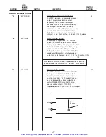
LCD MNTR

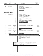
LCD GRAPHIC DISPLAY  SELECTION

0

LCD GRAPHIC DISPLAY is selectable from the
the following:

0:

RUN or STOP

   RUN

                       STOP

   Prg  

  DATA SET           Prg 

 DATA SET

    >> 

 ➮

  LED SET              >> 

 LED SET

1:

Bar graph (set frequency and output frequency)

2:

Bar graph (output frequency and output current)

3:

Bar graph (output frequency and motor torque)

Stop

Hz
Hz

ref

/F 

out

Stop

Hz
A

out

/I 

out

Stop

Hz
%

out

/Trq

100%

100%

100%

100%

200%

200%

Artisan Technology Group - Quality Instrumentation ... Guaranteed | (888) 88-SOURCE | www.artisantg.com

Summary of Contents for Fuji Electric AF-300ES

Page 1: ...s underutilized and idle equipment along with credit for buybacks and trade ins Custom engineering so your equipment works exactly as you specify Critical and expedited services Leasing Rentals Demos In stock Ready to ship TAR certified secure asset solutions Expert team I Trust guarantee I 100 satisfaction All trademarks brand names and brands appearing herein are the property of their respective...

Page 2: ...Instructions 1 2 350 Horsepower AF 300E TM Artisan Technology Group Quality Instrumentation Guaranteed 888 88 SOURCE www artisantg com ...

Page 3: ... located on or inside the Drive to alert people that dangerous voltage may be present General Information AF 300E Instructions WARNING CAUTION AND NOTES The following format is used on the equipment or found in this manual Read all labels and follow the directions on them whenever working on the equipment WARNING Denotes operating procedures and practices that may result in personal injury or loss...

Page 4: ...Upon Delivery Inspection Procedures 2 2 Drive Keypad Functions and Layout 2 3 Table 1 AF 300E Standard Specifications 2 3 Model Numbering System Diagram 2 7 Table 2 AF 300E Drive Dimensions 2 8 CE Labeled Products 2 9 Table 3 AF 300E Drive Ratings Efficiencies and Watts Loss 2 10 3 INSTALLATION GUIDELINES 3 1 Installation Environment 3 1 Installation Mounting Clearance 3 2 AF 300E Dimension Drawin...

Page 5: ...20 Hz must be approved by the Company WARNING Before disassembling disconnect and lock out power from the drive Failure to disconnect power may result in death or serious injury A bus charge light provides visual indication that bus voltage is present verify the bus voltage level by measuring the voltage between power terminals P and N using an analog meter Do not attempt to service the drive unti...

Page 6: ...o 1 0 microseconds CAUTION Because the ambient temperature greatly affects drive life and reliability do not install the drive in any location that exceeds the allowable temperature Leave the ventilation cover attached for temperatures of 40 degrees C or below and remove the cover for temperatures of between 40 104 F and 50 122 F degrees C 30 Hp and lower If the cover needs to be removed another t...

Page 7: ...on of drive local remote operation General data and specification for each drive are listed on the nameplate attached to the drive Refer to TABLE 1 for complete AF 300E drive specification listing All models are UL Listed and CSA Approved Nameplate shown larger than actual size Figure 2 1 NAMEPLATE DATA IDENTIFICATION INSPECTION PROCEDURES UPON DELIVERY Upon receipt of your drive inspect the equip...

Page 8: ...ped RUN Key This key is the RUN command in Keypad op eration run light will be illuminated at this time STOP Key This key is used for stopping operation If pressed when the Drive is running by external control fault Er6 will be displayed and Drive will coast to a stop UP DOWN Keys These keys increase or decrease the frequency or speed of the Drive When unit is in Program Setting Mode they change t...

Page 9: ...n inverse time characteristic 200 for 0 5 seconds 40 Hp and greater 150 for 1 minute duration inverse time characteristic 180 for 0 5 seconds Power Supply Rated Input AC Voltage 200 to 230 VAC 50 60 Hz 3 phase 1 2 to 30 Hp 380 to 400 VAC 50 Hz 3 phase 1 to 300 Hp CT 380 to 480 VAC 60 Hz 3 phase 1 to 300 Hp CT 460 480 VAC 60 Hz 3 phase 40 Hp and above variable torque applications only Voltage 10 15...

Page 10: ...ing Single cycle with continuous 7th speed Momentary Power Five selections available Refer to Power Supply Specification Loss Ride Thru High Low Limiter Output frequency upper and lower range limit 0 to 400 Hz 1 Hz step settings Bias Magnitude of the zero offset can be set from 0 to 100 of maximum frequency 1 Hz steps Gain Output frequency gain corresponding to the reference signal can be set from...

Page 11: ...n Auto restart mode Torque limiting mode Cycle completion pattern mode Auto reset mode Protective Functions Stall prevention Undervoltage Momentary power failure Overcurrent Drive overheating Overvoltage External faults Link error CPU malfunction Communication error Motor overload Ground fault electronic thermal Frequency Meter Output Signal Pulse frequency 6 to 100 times output frequency Analog 0...

Page 12: ...rm OH3 Drive internal temperature Er1 EE Prom malfunction Er2 Communication error Er3 CPU malfunction Er4 Link error Er5 Option malfunction Er6 Drive error at start up Er7 Missing motor connection Drive Input Output Display Forward Reverse Hld Bx X1 thru X5 Y1 thru Y5 Incoming reference voltages can be shown on LCD graphic display Charge Lamp LED Lights when DC Link capacitor voltage is present Ar...

Page 13: ...010 10 Hp 100 100 Hp Factory Installed Options N None X Keypad B to be determined Enclosure Type 1 NEMA 1 2 NEMA 12 4 NEMA 4 Product Revision A 1st Revision B 2nd Revision Minor Product Revision 1 1st Minor Revision 2 2nd Minor Revision AF 300E Model Numbering System Diagram Description 6K E N N N X N NN X N X N Artisan Technology Group Quality Instrumentation Guaranteed 888 88 SOURCE www artisant...

Page 14: ... N A 6KE 243005X1A1 D5515 1 560 10 24 x 5 91 x 5 71 8 4 7 5 13 0 10 16 5 6KE 243007X1A1 D5516 1 950 10 24 x 8 66 x 7 68 14 10 18 0 15 23 0 6KE 243010X1A1 D5517 2 375 10 24 x 8 66 x 7 68 14 15 24 0 20 30 0 6KE 243015X1A1 D5518 3 175 15 75 x 9 84 x 7 68 25 20 30 0 25 37 0 6KE 243020X1A1 D5519 4 000 15 75 x 9 84 x 7 68 25 25 39 0 30 44 0 6KE 243025X1A1 D5520 4 750 15 75 x 9 84 x 7 68 27 30 45 0 N A N...

Page 15: ... FRN75G9S 4EN D5649 15 245 134 125 FRN90G9S 4EN D5650 18 580 194 150 FRN110G9S 4EN D5651 21 890 194 200 FRN160G9S 4EN D5652 26 425 2775 250 FRN200G9S 4EN D5653 31 080 390 300 FRN220G9S 4EN D5654 36 400 390 Compatible RFI Filters Model No Cat No List Price Weight EFL015G94 CE Filter 1 2 Hp A3281 295 4 4 EFL040G94 CE Filter 3 5 Hp A3282 750 4 4 EFL075G94 CE Filter 7 5 10 Hp A3283 1 215 5 9 CE Compli...

Page 16: ...1 3 3 5 5 5 5 4 4 2 2 96 1 93 2 85 150 77 6KE 243005X1A1 B1 5 5 9 9 7 2 3 7 97 0 93 8 110 230 93 6KE 243007X1A1 B1 7 5 10 13 16 5 10 5 5 97 5 94 5 140 300 400 138 6KE 243010X1A1 B1 10 15 18 23 14 7 5 97 3 94 7 200 400 525 188 6KE 243015X1A1 B1 15 20 24 30 19 11 97 1 95 2 315 525 610 6KE 243020X1A1 B1 20 25 30 37 23 15 97 7 95 9 340 610 780 6KE 243025X1A1 B1 25 30 39 44 31 18 5 97 6 95 8 450 780 97...

Page 17: ...igure 3 1 these clearances are required to allow the heat generated by the drive to escape Install the drive perpendicular to the ground and with the lettering right side up If the drive is installed upside down or horizontally heat build up will occur Section 3 Installation Guidelines 3900 3300 333 100 1 8 100 CAUTION The mounting wall for the drive must be constructed of heat resistant material ...

Page 18: ... inches mm BUSHING SUPPLIED 1 26 32 0 87 22 2 52 64 9 69 246 10 24 260 28 7 0 24 6 0 28 7 0 28 7 0 24 6 4 33 110 3 78 96 0 24 6 4 53 115 0 87 22 2 52 64 Artisan Technology Group Quality Instrumentation Guaranteed 888 88 SOURCE www artisantg com ...

Page 19: ... inches mm BUSHING SUPPLIED 1 26 32 0 87 22 3 11 79 9 69 246 10 24 260 28 7 0 24 6 0 28 7 0 28 7 0 24 6 4 33 110 3 78 96 0 24 6 512 130 3 11 79 1 46 37 Artisan Technology Group Quality Instrumentation Guaranteed 888 88 SOURCE www artisantg com ...

Page 20: ...nsions in inches mm BUSHING SUPPLIED 1 26 32 0 87 22 3 7 94 9 69 246 10 24 260 28 7 0 24 6 0 28 7 0 28 7 0 24 6 5 91 150 5 35 136 0 24 6 5 71 145 3 7 94 2 05 52 1 26 32 Artisan Technology Group Quality Instrumentation Guaranteed 888 88 SOURCE www artisantg com ...

Page 21: ... 9 37 238 10 24 260 0 39 10 0 39 10 0 47 12 0 47 12 8 66 220 7 72 196 0 39 10 7 68 195 6 18 157 3 82 97 BUSHING SUPPLIED 0 87 22 6 18 157 2 26 57 5 2 07 52 5 1 81 46 0 47 12 Artisan Technology Group Quality Instrumentation Guaranteed 888 88 SOURCE www artisantg com ...

Page 22: ...G SUPPLIED 1 65 42 5 93 150 5 14 88 378 0 39 10 0 39 10 0 47 12 8 90 226 7 68 195 6 02 153 0 39 10 0 47 12 0 47 12 2 0 39 10 3 78 96 2 48 63 9 84 250 15 75 400 2 42 61 5 2 17 55 1 34 34 Artisan Technology Group Quality Instrumentation Guaranteed 888 88 SOURCE www artisantg com ...

Page 23: ...et Knock out hole 32 7 830 12 8 326 9 5 240 0 4 9 32 0 812 BACK PANEL 4 MB 0 3 4 1 105 AF 300E Back Panel Mounting Interior Watts Loss Hp CT 0 setting 10 setting Hp VT 0 setting 10 setting 35 40 650 850 40 850 1100 50 900 1050 AF 300E Thru Panel Mounting Interior Watts Loss Hp CT 0 setting 10 setting Hp VT 0 setting 10 setting 35 40 195 255 40 255 330 50 270 315 Artisan Technology Group Quality In...

Page 24: ...9 48 wire inlet Knock out hole 32 7 830 14 2 361 10 8 275 0 4 9 32 0 812 BACK PANEL 4 MB 0 3 4 1 105 AF 300E Back Panel Mounting Interior Watts Loss Hp CT 0 setting 10 setting Hp VT 0 setting 10 setting 50 900 1200 60 950 1150 AF 300E Thru Panel Mounting Interior Watts Loss Hp CT 0 setting 10 setting Hp VT 0 setting 10 setting 50 270 360 60 285 345 Artisan Technology Group Quality Instrumentation ...

Page 25: ...6 65 3 8 100 2 8 70 3 7 93 1 6 41 0 4 10 4 ø 1 9 48 wire inlet Knock out hole AF 300E Back Panel Mounting Interior Watts Loss Hp CT 0 setting 10 setting Hp VT 0 setting 10 setting 60 1000 1300 75 1050 1250 75 1150 1550 100 1300 1500 AF 300E Thru Panel Mounting Interior Watts Loss Hp CT 0 setting 10 setting Hp VT 0 setting 10 setting 60 300 390 75 315 375 75 345 415 100 390 450 Artisan Technology G...

Page 26: ... 4 1 105 3 ø 2 5 64 wire inlet Knock out hole NOTE Drive includes a separately mounted DC Link Reactor AF 300E Back Panel Mounting Interior Watts Loss Hp CT 0 setting 10 setting Hp VT 0 setting 10 setting 100 1500 1600 125 1700 1850 AF 300E Thru Panel Mounting Interior Watts Loss Hp CT 0 setting 10 setting Hp VT 0 setting 10 setting 100 450 480 125 510 555 NOTE Drive includes a separately mounted ...

Page 27: ...includes a separately mounted DC Link Reactor Dimensions 125 Hp 460 VAC Dimensions in inches mm AF 300E Back Panel Mounting Interior Watts Loss Hp CT 0 setting 10 setting Hp VT 0 setting 10 setting 125 1750 2000 150 1800 2000 AF 300E Thru Panel Mounting Interior Watts Loss Hp CT 0 setting 10 setting Hp VT 0 setting 10 setting 125 525 600 150 540 600 NOTE Drive includes a separately mounted DC Link...

Page 28: ... PANEL 4 M12 0 5 5 5 140 3 ø 2 5 64 s NOTE Drive includes a separately mounted DC Link Reactor AF 300E Back Panel Mounting Interior Watts Loss Hp CT 0 setting 10 setting Hp VT 0 setting 10 setting 150 2050 2350 200 2050 2300 AF 300E Thru Panel Mounting Interior Watts Loss Hp CT 0 setting 10 setting Hp VT 0 setting 10 setting 150 615 705 200 615 690 NOTE Drive includes a separately mounted DC Link ...

Page 29: ...ACK PANEL 4 M12 0 5 5 5 140 3 ø 2 5 90 NOTE Drive includes a separately mounted DC Link Reactor AF 300E Back Panel Mounting Interior Watts Loss Hp CT 0 setting 10 setting Hp VT 0 setting 10 setting 200 2850 3250 250 2800 3150 AF 300E Thru Panel Mounting Interior Watts Loss Hp CT 0 setting 10 setting Hp VT 0 setting 10 setting 200 855 975 250 840 945 NOTE Drive includes a separately mounted DC Link...

Page 30: ...0 2 4 60 4 ø 3 5 90 wire inlet Knock out hole 4 3 110 6 7 170 4 9 125 5 3 134 1 6 41 3 9 100 43 110 1 6 40 3 75 4 ø 1 9 48 wire inlet Knock out hole NOTE Drive includes a separately mounted DC Link Reactor AF 300E Back Panel Mounting Interior Watts Loss Hp CT 0 setting 10 setting Hp VT 0 setting 10 setting 250 3500 4000 300 3450 3800 300 3850 4450 350 3900 4300 AF 300E Thru Panel Mounting Interior...

Page 31: ...3 15 Keypad Mounting Hole Panel Cutting Dimensions in inches mm Artisan Technology Group Quality Instrumentation Guaranteed 888 88 SOURCE www artisantg com ...

Page 32: ...3 16 Notes Artisan Technology Group Quality Instrumentation Guaranteed 888 88 SOURCE www artisantg com ...

Page 33: ...Figure 4 3 4 4 for wiring connections See TABLE 4 for description of all terminals Make wire connections as shown in Figure 4 4 through 4 6 for desired mode of external operation through control circuit terminals See TABLE 4 for description of all terminals CAUTION The control circuit terminal wiring should be kept as far away as possible from the main power wiring to prevent opera tional error du...

Page 34: ... 3 or 4 4 See TABLE 5 for description of all terminals and TABLE 4 for recommended wire sizes Figure 4 3 TERMINAL BLOCKS Main Circuit Terminal Block Control Circuit Terminal Block 3 Connect the 3 phase motor wires to the U V and W terminals of the Main Circuit Terminal Block as shown in the appropriate view of Figure 4 3 or 4 4 See TABLE 5 for description of all terminals and TABLE 4 for recommend...

Page 35: ... 200 210 253 1 0 2 321868 4 1 36923 300 225 200 250 304 304 3 0 2 36929 4 2 171500 2 350 400 250 300 377 377 250 2 171500 2 4 2 171502 2 400 400 300 350 415 415 300 2 171500 2 4 2 171502 2 500 500 In variable torque applications Function Code 86 Motor Hp Capacity needs to be changed to Set Drive Hp vs Load Hp 40 Hp and above is 460 480 VAC input VT applications only 1 Device ratings such as system...

Page 36: ...ctory Figure 4 4 1 2 30 Hp TERMINAL BOARDS Control Terminal Board 1 2 30 Hp FUSES Reference UL power circuit protection requirements Refer to Table 4 on page 4 4 UL Listed non time delay fuses should be used Power Terminal Board Refer to Dynamic Braking Table on Page 4 16 NOTE P1 P terminals are jumpered together at the factory Artisan Technology Group Quality Instrumentation Guaranteed 888 88 SOU...

Page 37: ... Remove jumper from between terminals FWD and CM NOTE Wiring connections for operation with kaypad reference control CM FWD and CM THR terminals are jumpered together at the factory Power Terminal Boards NOTE A DC Link Reactor is also shipped for connection between terminals P1 P 100 Hp and greater Artisan Technology Group Quality Instrumentation Guaranteed 888 88 SOURCE www artisantg com ...

Page 38: ...se Counter _ _ W V U P DB N P1 FAULT 30A 30B 30C Power On Power Off Breaking Section 15 to 30 HP Y1 Y2 Y3 Y4 Y5 E G CME Ground Breaking Unit Breaking Resistor 1 2 N DB P P N P P DB 1 2 Any additional normally closed protective interlocks should be added in series Motor Ground Braking Section 1 2 to 10 HP P DB 1 2 Customer supplied power for contactor coil Circuit Breaker _ R C Terminal 11 should n...

Page 39: ...y closed protective interlocks should be added in series Terminal 11 should not be connected to either CM and or CME Refer to the Dynamic Braking Table on Page 4 13 DC Link Reactor furnished and mounted external on 100 Hp and higher Motor Ground Braking Section Customer supplied power for contactor coil Curcuit Breaker _ R C R0 T0 Control Power Input V1 VOLTAGE REF 0 TO VDC VS 3 2 1 2W Speed Pot 1...

Page 40: ...ty may be lost 12 Frequency Setting When 0 to 10 VDC 0 to 5V is input the maximum frequency is Voltage Input reached at 10 VDC 5V and is proportional to output frequency down to 0 VDC Input impedance is 22K ohm Must be isolated source 13 Frequency Setting Regulated 10 VDC power supply for frequency setting potentiometer Voltage Output Term 10mA or less 13 to terminal 11 C1 Frequency Setting When t...

Page 41: ...ance of 10KΩ can be connected in parallel FMP Frequency Meter Pulse frequency output equal to drive output frequency multiplied Connection Points by the set value of Function Code 43 Meter connects between FMP Pulse and CM AX1 Run Relay Dry Contact is closed when the drive is running Contact rating AX2 Contact Output resistive load 250 VAC 0 3 Amps Only applicable to 40 Hp and greater 30A Fault Re...

Page 42: ...tts HP Lbs KG Inches MM Inches MM Inches MM Loss 100 55 25 9 85 250 7 88 200 5 95 151 95 125 70 6 32 11 03 280 8 67 220 6 7 171 94 150 88 40 14 17 360 7 48 190 6 97 177 100 200 99 45 13 79 350 8 67 220 6 7 171 115 250 110 50 12 21 310 9 06 230 7 13 181 140 300 110 50 12 61 320 9 06 230 7 9 201 160 DETACH THE FACTORY INSTALLED JUMPER IF REQUIRED When using the circuit shown in Figure 4 8 it is nece...

Page 43: ...ST BE OPEN DURING POWER UP OR Er6 TRIP WILL OCCUR 1 CAUTION REMOVE JUMPER FROM BETWEEN TERMINALS THR AND CM WHEN THERMAL INTERLOCKS ARE USED 2 CAUTION REMOVE JUMPER FROM BETWEEN TERMINALS FWD AND CM 01 1 REMOTE 33 JOG ACCEL TIME SETTING 34 JOG DECEL TIME SETTING 20 JOG SPEED FREQUENCY SETTING STOP RUN JOG E 2 1 30A 30B Y1 Y2 Y5 C1 FMA FMP X1 X2 X3 X4 X5 RST 30C CME Y2 Y4 11 12 13 CM FWD REV CM THR...

Page 44: ...A is selected and pro grammed into Function Code 47 Used to avoid Er6 after power failure and re applica tion of main AC power WARNING Personal safety must be considered when activating this function Automatic Restart Circuit Connection OUTPUT TERMINALS Y1 Y5 INPUT TERMINAL FWD REV X1 X5 HLD BX THR RST 27 VDC MAX 50 mA MAX 0 to 10 VDC 4 to 20 mA dc 1 5K Ohms 2 WATT 22K Ohms 22K Ohms 250 Ohms Artis...

Page 45: ...A N A BUILT IN N A 6KE 34DBR005 1 0 4 160 0 6KE 243007X1A1 B1 100 150 5 20 SEC 3 5 15 SEC BUILT IN N A 6KE 34DBR007 1 0 8 80 0 6KE 243010X1A1 B1 100 150 5 10 SEC 3 5 7 SEC BUILT IN N A 6KE 34DBR010 1 0 9 60 0 6KE 243015X1A1 B1 20 150 5 10 SEC 3 5 7 SEC 6KE 34DBU030 1 6KE 34DBR015 1 1 4 48 0 6KE 243020X1A1 B1 20 150 5 10 SEC 4 8 SEC 6KE 34DBU030 1 6KE 34DBR020 1 1 4 48 0 6KE 243025X1A1 B1 20 150 5 ...

Page 46: ...breaker There is no need to match the phase when connecting If the power supply is overvoltage category 3 place the devices to limit overvoltage below 2 5 kV as shown LI L2 L3 Isolation Transformer Inverter Inverter Varistor Surge Absorber LI L2 L3 Figure 4 13 MAIN CIRCUIT WIRING FOR CE MARK Artisan Technology Group Quality Instrumentation Guaranteed 888 88 SOURCE www artisantg com ...

Page 47: ...is running If a test run is desired press the DOWN key to change the flashing display of 60 00 Hz frequency setting to 5 00 Hz Within 4 seconds press the FUNC DATA key to set the new setting into software Conduct the test run and check for smooth rotation and correct direction of the motor Figure 5 1 KEYPAD PANEL DISPLAY WHEN AC POWER IS APPLIED Section 5 Drive Operation Table 6 Keypad and Display...

Page 48: ...E 1 05 ACC TIME 1 6 00S 0 01 3600 Press UP Key to Increase Accel Time Key Can Shift Decimal Point Press PRG Key to Return to Operation Mode STOP PRG DATA SET LED SEL Setting Blinks until FUNC DATA Key is pressed setting it in Software and returning to the next screen 05 ACC TIME 1 6 00S 10 00S Store F D KEY 06 DEC TIME 1 07 TRQ BOOST 1 08 ELCTRN OL 09 OL LEVEL Press FUNC DATA Key to indicate setti...

Page 49: ...3 60 Hz 04 OV 05 6 00S Press FUNC DATA Key to indicate setting and range of setting Setting Blinks until FUNC DATA Key is pressed setting it in Software and returning to the next screen 06 6 00S 07 0 0 08 1 09 14 5A STOP PRG DATA SET LED SEL Continue through Function Codes or Press PRG Key to Return to Operation Mode 05 ACC TIME 1 6 00S 10 00S Store F D KEY 05 ACC TIME 1 6 00S 0 01 3600 DATA CHECK...

Page 50: ...TOR ON OFF REV HLD FWD BX THR RST X1 X2 X3 X4 X5 12 0 0 V V1 0 0 V C1 4 0 ma Y2 Y3 Y1 Y4 Y5 TIME Oh UNIT S00000 KEYPAD K00000 Press FUNC DATA Key to Display Program Mode Press FUNC DATA Key to Display Input Terminal Points Press Key to Display Output terminal points Press Key to Display Reference Inputs STOP PRG DATA SET LED SEL Program Mode Checking Input Output Signals LCD Graphic Display at Pow...

Page 51: ...GROUND FAULT TIME TRQ TEMP h C SHOCK LOAD EXCESS LOAD TRQ BOOST SHORT CIRCT O C 3 O C 3 DATA CHECK I O CHECK TRIP IND CK TRIP FACTOR 0 LV 1 0H2 2 0C1 3 LV Hz Hz A V Fout Fref Iout Vout Keypad fault indication PressFUNC DATA key to display Program Mode Press FUNC DATA key Press FUNC DATA key The following displays would only be accessible after a fault and before main power is removed LCD graphic d...

Page 52: ...imit Reached Normal Condition V L U V 3 Normal Condition Voltage Limit Reached Undervoltage Condition 4 T L Normal Condition Torque Limit Reached Press key to 1 2 3 4 Exploded view of Circumstances of Trip Display from previous page TIME TRQ TEMP h C Circumstances of Trip Artisan Technology Group Quality Instrumentation Guaranteed 888 88 SOURCE www artisantg com ...

Page 53: ...dicates that multiple faults occurred at the same time Press UP key to acces the second or third fault Press Key to Display last 3 Faults and Current Fault Press Key to Display Input Terminal Press Key to Display Status of the Trip Press Key to Return to Program Mode Press FUNC DATA Key to Indicate Operating Conditions to be reviewed LED Display on Digital Monitor Press Key to Display Output Termi...

Page 54: ...IND CK TRIP FACTOR 0 LV 1 0H2 2 0C1 3 LV STOP PRG DATA SET LED SEL Press DOWN Key to scroll to Trip Indication Check Press FUNC DATA Key to Display the last 3 Faults and Current Fault Accessing Fault History Press FUNC DATA Key to Display Program Mode Artisan Technology Group Quality Instrumentation Guaranteed 888 88 SOURCE www artisantg com ...

Page 55: ...5 9 Notes Artisan Technology Group Quality Instrumentation Guaranteed 888 88 SOURCE www artisantg com ...

Page 56: ...ration Time 1 07 Torque Boost 1 08 Electronic Thermal Overload Relay Select 09 OL Level 10 Restart After Instantaneous Power Failure 11 High Limiter 12 Low Limiter 13 Bias Frequency 14 Frequency Setting Signal Gain 15 Torque Limiter Driving 16 Torque Limiter Braking 17 DC Brake Starting Frequency 18 DC Brake Level 19 DC Braking Time 20 Multistep Frequency Setting 1 21 Multistep Frequency Setting 2...

Page 57: ...Language 79 LCD Display Brightness 80 Function Block 81 94 81 Motor Sound 82 Auto Restart Restart Time 83 Fall Rate 84 Auto Reset Times 85 Auto Reset Reset Interval SpecialFunctions cont d MotorCharacteristics 86 Motor 1 Capacity 87 Motor 1 Rated Current 88 Motor 1 No Load Current 89 Motor 2 Rated Current 90 Motor 1 Impedance Tuning 91 Motor 1 Impedance R1 Setting 92 Motor 1 Impedance X Setting Sp...

Page 58: ...5 12 Notes Artisan Technology Group Quality Instrumentation Guaranteed 888 88 SOURCE www artisantg com ...

Page 59: ... OPERATION METHOD 0 RUN STOP and RESET commands can be supplied by two different methods Keypad local or terminal strip remote 0 Keypad operation RUN STOP keys 1 Terminal strip operation Keypad STOP key active 2 Terminal strip operation Keypad STOP key inactive NOTE Remote local operation can be toggled by pressing RESET and STOP keys simultaneously when the drive is in the STOP condition NOTE Con...

Page 60: ...conds Note that this 20 0 setting defines the time to accelerate from 40HP and greater zero to maximum frequency Function Code 02 Smaller frequency steps will result in shorter acceleration times because the rate is constant Example ACC TIME 1 10 seconds MAX Hz 60 The acceleration rate is 6 Hz sec therefore a step from 8 to 42 Hz would take 42 8 6 5 6 seconds 06 DEC TIME 1 DECELERATION TIME 1 6 0 ...

Page 61: ...vate Function Code 90 Tuning to reset Function Code 91 92 08 ELCTRN OL ELECTRONIC OVERLOAD 1 The Drive s Electronic Overload can be selected to help protect the motor from thermal overload due to various operating conditions Selection should be based on operating conditions type of load motor thermal characteristics and the applicable NEC and local electrical code requirements The motor thermal ch...

Page 62: ...p 30A motor were applied to a 30 Hp 45A drive you would change Function Code 09 from 45 to 30 amps to protect the motor The setting range is approximately 20 to 135 of rated drive current 10 RESTART RESTART 0 The AF 300E family of Drives are designed to tolerate an AC line voltage dip to 165V 230 VAC 310V 230 VAC 400V 575 VAC 70 for 15 msec at 85 of full load without any disturbance in output powe...

Page 63: ...iter the H Limiter takes effect 10 cont d 0 Restart inactive Drive will trip and alarm when low voltage point is detected 1 Restart inactive Drive will trip but will not alarm until voltage recovers 2 Restart active Normal smooth recovery method drive will continuously decrease speed until voltage recovers then accelerate normally back to set point 3 Restart active Drive stops motor coasts when lo...

Page 64: ...from 0 to 400 Hz WARNING Bias is operational only when frequency setting method is analog Function Code 00 1 or 2 When the drive does not have a run command the reference or output flashes on the display see Function Code 62 When bias is operational and the speed reference is zero the display flashes bias frequency When a RUN command is given the motor runs at the bias setting Bias Frequency Setti...

Page 65: ...he drive will provide in the driving direction i e delivering power It is set as a percentage of rated torque and is adjustable from 20 to 180 Setting this Function Code to 999 will remove the limit This Function Code can be used to avoid the breakdown torque region of the motor see related Function Code 86 concerning motor capacity CAUTION If this Function Code is set too low when compared to the...

Page 66: ...ic braking capability and deceleration time proportionate to load inertia to avoid overvoltage faults 17 DC BRK Hz DC INJECTION BRAKE STARTING Hz 0 0 DC injection braking can provide an effective means of stopping the motor especially after the motor has already reached a low speed This setting determines the frequency at which dc braking takes affect during a deceleration Adjustable from 0 to 60 ...

Page 67: ...ts temperatures can build up to very high levels in a short period of time possibly resulting in motor damage Seven 7 digitally preset speeds can be programmed into Function Codes 20 through 26 These can be used as part of a pattern operation see Function Code 65 or individually selectable through switching of control terminals X1 X2 and X3 see Function Code 32 20 MULTI Hz 1 MULTI STEP FREQUENCY 1...

Page 68: ...he drive has a pre programmed electronic 15 Hp and UP thermal overload protection function for the 1 dynamic braking resistors for Drives rated UP TO 10 Hp 10 Hp and below Drives rated 15 Hp and above or for non standard braking resistor packages use a thermal overload sensing device 0 Inactive 15 Hp and greater or non standard DB resistors 1 Active for internal braking resistor up to 10 Hp MULTI ...

Page 69: ...ing has the effect of reducing speed fluctuations in the presence of overhauling loads A negative setting might also be used when trying to get two motors with a common shaft to load share better 29 TRQ VECTOR TORQUE VECTOR CONTROL 0 Sensorless torque vector control is a recently developed control strategy which provides much of the performance of AC flux vector drives without the cost of an expen...

Page 70: ...accurately enough to provide the specified performance However torque vector control may still be used if performance is adequate for the application For your convenience we have pre installed the parameters for the 4 pole GE Energy aver motor with horsepower rating corresponding to the drive rating If you are using any other motor you should set Function Code 04 Rated Voltage 1 and Function Code ...

Page 71: ...displayed INPUT TERMINAL FUNCTIONS 32 X1 X5 TERM X1 THROUGH X5 TERMINAL FUNCTIONS 0000 This Function Code determines the functions of the X1 through X5 contact inputs on the terminal block It is adjustable from 0000 to 2223 Each of the four digits has a separate meaning as defined below X1 and X2 function selected by 1st digit 0 Multistep speed selection four steps 1 UP DOWN control 1 start from 0...

Page 72: ... is set by Function Code 18 Operation command takes precedence RUN FWD REV While X4 to CM is ON if FWD to CM is ON dc brake reset As dc current continues to flow to the motor during the X4 to CM ON period be careful of motor temperature rise When long periods of dc braking are required measure the motor s temperature continuously DC brake time Function Code 19 is ignored CAUTION Motor may overheat...

Page 73: ...ect 3 and install a wire jumper between Terminal X5 and CM ACCEL DECEL TIMES 33 ACC TIME 2 ACCELERATION TIME 2 10 0 Adjustable from 0 01 to 3600 seconds 30Hp and less 100 40 Hp and greater 34 DEC TIME 2 DECELERATION TIME 2 10 0 Adjustable from 0 01 to 3600 seconds 30Hp and less 100 40 Hp and greater NOTE 100 Seconds for 40 Hp and greater Acceleration Deceleration times 2 through 4 are identical in...

Page 74: ...n Code 32 equals 1 and X5 CM contacts are closed NOTE When set at zero 0 the maximum output voltage will follow the input AC line voltage 30 Hp lower only 41 TRQ BOOST2 TORQUE BOOST 2 2 0 Torque boost for motor 2 can be set to optimize the V Hz characteristics of the drive according to the type of load the motor will see Motor 2 Function Codes become active when Function Code 32 equals 1 and X5 CM...

Page 75: ... approxi mately 5 to 12 VDC by changing Function Code 44 from 50 to 120 respectively The voltage will be accurate to 5 The peak voltage of the pulses will be approximately 15 6 VDC regardless of this setting only the average output voltage is changed Ex Vavg 12V x 100 setting 10V 120 CAUTION The minimum load impedance which should be placed between the FMP and CM terminals is 5 000 ohms 45 FMA V A...

Page 76: ...o configure its corresponding output 0 Drive running RUN see Function Code 57 1 Frequency at reference FAR see Function Code 48 2 Frequency level detection FDT see Func tion Codes 49 and 50 3 Overload early warning OL see Function Code 51 4 Undervoltage detection LU 5 Keypad operation mode 6 Torque limiting see Function Codes 15 and 16 7 Drive stopped STOP 8 Auto restarting see Function Code 10 9 ...

Page 77: ...ff On On Off On Off 5 6 7 On On On Off On On On Off On Cause of trip Terminal Y2 F Y3 F Y4 F Y5 F 0 Off Off Off Off 1 OC1 Off Off Off On 2 OC2 Off Off On Off 3 OC3 and EF Off Off On On 4 OU1 OU2 OU3 Off On Off Off 5 LU Off On Off On 6 OL Off On On Off 7 OLU Off On On On 8 OH1 OH3 On Off Off Off 9 OH2 dbH On Off Off On 10 FUS On Off On Off 11 Er1 Er3 On Off On On 12 Er2 On On Off Off 13 Er4 On On O...

Page 78: ...elay unit to allow connection to system control circuitry Adjustable from 0 0 to 10 Hz in 0 1 Hz steps 49 FDT LEVEL FREQUENCY DETECTION THRESHOLD 60 The signal is on when the output frequency exceeds the detection level setting This is an open collector output and can be used in conjuction with a relay unit to allow connection to system control circuitry Adjustable from 0 to 400 Hz Far Hyster Far ...

Page 79: ...h a relay unit to allow connection to system control circuitry Adjustable from approx imately 20 to 135 of drive rated current NOTE This is a timed function similar to Function Code 08 and 09 ELCTRN OL 52 53 59 FUNCTION CODE BLOCK DISPLAY 0 This setting determines whether or not Function Codes 53 through 59 will be displayed and available for adjustment 0 Function Codes 53 through 59 NOT displayed...

Page 80: ...CY JUMP HYSTERESIS 3 This setting determines the hysteresis jump width of the jump frequency setting Adjustable from 0 to 30 Hz Example Function Code 53 set at 20 Hz Function Code 56 set at 4 Hz Output frequency will reach 18 Hz jump to 22 Hz and continue ramping if input reference is set above 20 Hz On a decel output frequency will reach 22 Hz and jump to 18 then continue to decel Hysteresis Hyst...

Page 81: ... 59 FILTER REFERENCE SIGNAL FILTER 0 05 This Function Code is used to set the time constant for the input filter in order to eliminate the effects of noise present in the analog signals voltage and current references If the time constant set point is too long the response to changes in analog commands will become inadequate for the required performance level Adjustable from 0 01 to 5 00 seconds 60...

Page 82: ...Torque Limiter Driving Setting Frequency Hz 7 Torque Limiter Braking Setting Frequency Hz 8 Calculated torque Setting Frequency Hz LED LCD MONITOR 61 LED MNTR 1 LED MONITOR SELECTION 1 0 Setting from 0 to 8 for a total of nine 9 selectable indicating modes See table below 62 LED MNTR 2 LED MONITOR SELECTION 2 0 This setting determines the LED display in the STOP Mode of operation 0 Setting value 1...

Page 83: ...UN or STOP RUN STOP Prg DATASET Prg DATASET LEDSET LEDSET 1 Bar graph set frequency and output frequency 2 Bar graph output frequency and output current 3 Bar graph output frequency and motor torque Stop Hz Hz Fref F out Stop Hz A F out I out Stop Hz Fout Trq 100 100 100 100 200 200 Artisan Technology Group Quality Instrumentation Guaranteed 888 88 SOURCE www artisantg com ...

Page 84: ...n deceleration 71 STAGE 6 times Function Codes 5 6 33 through 38 72 STAGE 7 and a maximum duration running time of 6 000 seconds each Code FWD REV ACC DECEL F1 FWD ACC1 DEC1 0 00S F1 F2 FWD ACC2 DEC2 0 00S F1 F3 FWD ACC3 DEC3 0 00S F1 F4 FWD ACC4 DEC4 0 00S F1 R1 REV ACC1 DEC1 0 00S F1 R2 REV ACC2 DEC2 0 00S F1 R3 REV ACC3 DEC3 0 00S F1 R4 REV ACC4 DEC4 0 00S F1 Example Function Code 66 set at 15 ...

Page 85: ...o set frequencies 1 through 7 in ascending numerical order only To set motor s direction of rotation and acceleration deceleration time utilize Function Codes 66 through 72 If each subsequent frequency is higher or lower than the present frequency the acceleration or deceleration time will be auto matically selected based on the Stage setting Function Codes 66 through 72 Time Stage1 Time Stage2 Ti...

Page 86: ... on the timer is less than the time required for the acceleration deceleration conditions it will proceed to the next process before the original set frequency is reached f f t t Stage 1 Stage 2 Stage 1 Stage 2 Stage 1 t f Forward Reverse Function Code 06 setting Deceleration Time Function Code 05 setting Acceleration Time Stage 2 06 05 Stage 1 Stage 2 Stage 2 t Timer Required acceleration time du...

Page 87: ...t RUN input will start operation from pattern stage 1 NOTE The RESET key only functions when the drive is stopped or paused Stage 1 Stage 2 Stage 3 Stage 4 Stage 5 Stage 6 Stage 7 t Output Frequency Output Frequency Stage 1 Stage 2 During this span time is not counted Remaining operation time for Time 1 STOP RUN RUN Output Frequency Stage 1 Stage 2 Stage 1 Stage 3 Stage 2 RUN STOP RESET RUN Artisa...

Page 88: ...tart operation FWD CM OFF Stops timer operation Pause RESET key Timer reset NOTE The RESET key only functions when the drive is stopped or paused Example 1 Stage 1 Stage 2 Stage 3 Stage 4 Stage 5 Stage 6 Stage 7 t FWD CD Output Frequency Output Frequency Stage 1 Stage 2 Stage 1 Stage 3 Stage 2 t FWD CM Artisan Technology Group Quality Instrumentation Guaranteed 888 88 SOURCE www artisantg com ...

Page 89: ...LOC REVERSE DIRECTION LOCK OUT 0 Prevents the drive from operating in a reverse direction 0 Inactive 1 Active Will not allow the motor to run in reverse direction even in pattern mode 77 DATA INIT DATA INITIALIZATION 0 Allows resetting Function Codes to factory settings 0 Manual setting value customized drive settings 1 Return to factory default setting values 78 LANGUAGE LANGUAGE SELECTION 1 Allo...

Page 90: ...quency output reaching zero to 30HP and less frequency output restarting 0 5S See Function Code 10 Restart 40HP and greater 0 0 TO 5 0 Time in seconds 83 FALL RATE RATE OF FALL 10 00 This Function Code sets the deceleration rate for the motor during lead in when Function Code 10 RESTART is active and a momentary power failure occurs 0 Deceleration occurs for the set decel time 1 TO 100 Deceleratio...

Page 91: ...TOR 1 NAMEPLATE FULL LOAD CURRENT RATED 2000 AMPS 88 MOTOR 1 Io 0 00 TO MOTOR 1 NO LOAD CURRENT Magnitizing 2000 current 89 MOTOR 2 Ir 0 00 TO MOTOR 2 NAMEPLATE FULL LOAD CURRENT RATED 2000 AMPS 90 TUNING MOTOR TUNING 0 This Function Code is used to tune the primary resistance and inductance of the motor 0 Inactive 1 Active WARNING Ensure the motor is connected free to rotate and at a standstill U...

Page 92: ...I X1 X2 XM are motor values Cable X is inductance of cable between drive and motor V is rated motor voltage 93 DD FUNC 1 DO NOT USE 94 DD FUNC 2 DO NOT USE 95 DATA PRTC DATA PROTECTION 0 Once the Function Codes have been set the data protection can be activated and prevent any further changes 0 Not protected changeable 1 Protected change prevented Press and UP Key together to change Function Code ...

Page 93: ...nd P then megger to ground 3 Use a high resistance range type tester to conduct a continuity test on the control circuits and not a megger or a buzzer PERIODIC PARTS REPLACEMENT The life of the drive will vary according to the installation environment and the amount of running time However if continuous operation is within the allowable limits the life of the dc Link capacitor is approximately fiv...

Page 94: ...lation on cooling fins Clean and blow out with compressed air cooling fan or on the control board Screws Check for any loosening Retighten as needed Connectors the current the amount of error will be large if the frequency is low Because of this always use a CT with as large a capacity as possible See the following chart and Figure 7 2 for recommended measurement devices MEASUREMENT POINTS AND MET...

Page 95: ...7 3 Figure 7 2 MEASUREMENT LOCATIONS AND DEVICES EXAMPLE Artisan Technology Group Quality Instrumentation Guaranteed 888 88 SOURCE www artisantg com ...

Page 96: ...7 4 Notes Artisan Technology Group Quality Instrumentation Guaranteed 888 88 SOURCE www artisantg com ...

Page 97: ...rnal temp X DB Dyn Brk Protects the dynamic brake resistor from over heating d b H X Electronic thermal overload Protects the Drive with electronic overload Protects the motor with electronic overload sense Range of setting 20 to 135 of Drive rated current O L U O L X Inside fuse Detects the DC bus failed fuse 15 Hp and above F U S X External Stops Drive by an external alarm signal O H 2 X Memory ...

Page 98: ... SPD Operating conditions that need to be reviewed DECEL TIME EXCESS LOAD TRQ BOOST SHORT CIRCT GROUND FAULT Drive Display OVERCURRENT OC2 during DEC Operating conditions that need to be reviewed OVERCURRENT OC1 during ACC Operating conditions that need to be reviewed GROUND FAULT ACCEL TIME EXCESS LOAD TRQ BOOST SHORT CIRCT Drive Display PROTECTIVE FUNCTIONS Individual listings drive displays Pro...

Page 99: ...rotective Function Function Explanation LED Display Remarks Alarm RY 30A B C Ground Fault Grounded output The protecction is effective for Drive output terminals U V W EF Grnd Fault X Over voltage Protects the Drive when the DC bus voltage reaches the momentary overvoltage protection level by a braking operation Drive cannot protect against an input line overvoltage O U 1 O U 2 O U 3 At accel At d...

Page 100: ...e resistor from over heating d b H X OVER HEAT dbH Drive Dynamic Braking Operating conditions that need to be reviewed OVER HEAT OH1 drive heatsink Operating conditions that need to be reviewed OVER HEAT OH3 drive PCB Operating conditions that need to be reviewed Over heat Protects the Drive against overheating caused by overload operation cooling fan failure abnormal high ambient temperatures etc...

Page 101: ...d above F U S X OVER LOAD OL Motor Overload Operating conditions that need to be reviewed OVERLOAD OLU Drive Overload Operating conditions that need to be reviewed INSIDE FUSE FUS DC Fuse Open Operating conditions that need to be reviewed Electronic Protects the Drive with electronic overload O L U X thermal Protects the motor with electronic overload sense O L overload Range of setting 20 to 135 ...

Page 102: ... Function Function Explanation LED Display Remarks Alarm RY 30A B C Keypad communication Detects a continuous communication error between control PCB and keypad panel If Inverter is operated from control circuit terminals it will continue to operate without an alarm signal enen if E r 2 occurs When communication is restored the E r 2 display will be cleared E r 2 X COMMUNICATION ERROR Er 2 keypad ...

Page 103: ...isplay Protective Function Function Explanation LED Display Remarks Alarm RY 30A B C Protective Function Function Explanation LED Display Remarks Alarm RY 30A B C Protective Function Function Explanation LED Display Remarks Alarm RY 30A B C Option communication Detects a continuous communication error between control PCB and option PCB E r 4 X CPU error Detection of a CPU malfunction E r 3 X Optio...

Page 104: ... LED Display Remarks Alarm RY 30A B C Prevent stall Prevents OC trip by ceasing frequency output at high current when torque limit is disabled and drive is accelerating or when high impact loads are applied to the motor Second by decreasing frequency level when torque limit is activated and its value is being exceeded during steady state operation and load acceleration Operating Proc Error Detects...

Page 105: ...n method Please contact GE Fuji There is a possibility of drive failure or a motor noise problem Please contact GE Fuji Increase the set time No No Is the acceleration time setting too short for the load Can the acceleration time be increased Yes Reduce the load or increase the drive capacity No Yes No Yes Can the torque boost setting be reduced No No Reduce the torque boost setting No E F No Ther...

Page 106: ...ing resistor installed and activated Failure in the drive or misoperation due to electrical noise can be considered Contact GE Fuji No Increase the timed setting Decrease until the failure does not occur Can the acceleration time be increased Can the load inertia be decreased No Yes Yes Investigate braking unit braking resistor or DC brake for correct connection rating and control settings Will ac...

Page 107: ...in the same power system Yes Investigate the power system and revamp to satisfy the system specification No Is the power transformer rated at the correct KVA Failure in Drive Reset and continue operation Yes Replace the defective compo nent or repair the poor connection Yes Failure in the drive control circuit or noise related mis operation can be considered Contact GE Fuji Is the main DC circuit ...

Page 108: ...s the possibility of drive failure or noise related misoperation Contact GE Fuji Are the cooling fans in the drive operat ing Is the passage of the drive cooling air obstructed Is the ambient temperature within the specified limit Failure in the drive or noise related misoperation can be considered Contact GE Fuji Bring the ambient condition to within the specified limit No Yes No No Yes Yes No No...

Page 109: ...correctly Set to the correct level F U S Short circuit might be in the drive Contact GE Fuji 8 DC Link fuse blown Is the load too large No Install an external thermal overload relay in the motor power circuit Failure in the drive or noise caused misoperation can be considered Contact GE Fuji Reduce the load or increase the drive capacity Yes Yes No No Yes Artisan Technology Group Quality Instrumen...

Page 110: ...se close to the Drive s control printed circuit card Check for contami nation due to the environment Keypad Communication Memory Error Error CPU Error E r 2 Check for contamination due to the environment Is keypad connector properly inserted This indicates drive failure Contact GE Fuji Output circuit U V W disconnected or open circuit No Yes Yes No Yes No No Yes Yes Insert the keypad correctly Rep...

Page 111: ...rs No Is the wiring between FWD or REV CM terminals connected correctly Poor contact in switch or relay Has the motor been locked Release the lock No No Set the frequency by pressing UP key or DOWN key No Do the drive output terminals U V W have applied voltage Yes Yes Yes Yes Yes Yes Is high limiter or frequency set signal below the starting frequency The drive is thought to have failed Contact G...

Page 112: ... failure in the drive or noise related problems Contact GE Fuji No Motor speed change is very small under these conditions 1 Wrong setting of FC13 bias frequency FC14 gain for frequency setting 2 If using terminal 12 V1 and C1 check polarity inputs to insure they are correct and do not offset 3 During torque limiting or current limiting with excessive load Yes No Determine which frequency method i...

Page 113: ...Is the V Hz characteristics suitable for the motor Abnormal motor heating Reduce the load or increase motor capacity Failure in motor possible Reduce the load Wk2 or increase the drive capacity Contact GE Fuji Increase or de crease the torque boost setting Is a special motor in use Make the wire size between the drive and the motor larger or shorten the wiring distance Is the torque boost set corr...

Page 114: ...8 18 AF 300E Adjustable Frequency Drive Control Block Diagram Artisan Technology Group Quality Instrumentation Guaranteed 888 88 SOURCE www artisantg com ...

Page 115: ...ive Warranty period is 12 months after installation or 18 months after shipment from the Company whichever occurs first Before calling the number at left to determine warranty status the drive serial number will be required This is located on the drive nameplate If the drive is still under warranty further information will be required per the In Warranty Failure Checklist shown on page 9 2 of this...

Page 116: ...es No OutputStarter Yes No MotorOverloads Yes No ControlTerminalsUsed circleifused THR X1 X2 X3 X4 X5 30A 30B 30C RST BX FWD REV C1 V1 11 12 13 Y1 Y2 Y3 Y4 Y5 AX1 AX2 HLD FunctionCodesDifferentFromFactorySettings FunctionCode Setting FunctionCode Setting FailureMessage seeSection5 LatestFault PreviousFaults NoMessage Hz 1 A 2 V 3 After all of the Checklist information is acquired contact the follo...

Page 117: ...8 x 1 1 0 455 G9PPCB185 1 9 5 x 8 x 1 1 0 455 G9PPCB220 1 9 5 x 8 x 1 1 0 455 Capacitor Unit G9CU075 330uf 1 4 x 2 x 2 0 44 0 2 G9CU15 330uf 1 7 5 x 1 5 x 2 0 44 0 2 G9CU22 30uf 1 7 5 x 1 5 x 2 0 44 0 2 G9CU37 330uf 1 7 5 x 1 5 x 2 1 0 46 G9CU55 2700uf 1 3 x 3 x 3 1 0 46 G9CU75 3900uf 1 3 x 4 x 4 2 0 91 G9CU11 3300uf 1 3 x 4 x 4 2 0 91 G9CU150 4700uf 1 3 x 4 x 4 2 0 91 G9CU185 4700uf 1 4 x 4 x 4 2...

Page 118: ...E 1 9 x 6 x 2 5 1 0 455 G9PPCB437CE 1 9 x 6 x 2 1 0 455 G9PPCB455CE 1 8 5 x 7 5 x 1 1 0 455 G9PPCB475CE 1 10 x 8 x 1 1 0 455 G9PPCB411CE 1 10 x 8 x 1 1 0 455 G9PPCB4150CE 1 10 x 8 x 1 1 0 455 G9PPCB4185CE 1 10 x 8 x 1 1 0 455 G9PPCB4220CE 1 10 x 8 x 1 1 0 455 Capacitor Unit G9CU415 270uf 1 7 5 x 1 5 x 2 0 44 0 2 G9CU422 330uf 1 7 5 x 1 5 x 2 0 44 0 2 G9CU437 330uf 1 2 25 x 3 x 3 1 0 455 G9CU455 15...

Page 119: ... 3 6 2 75 X 3 X 1 0 34 0 16 SCK78P122D205K5 1200V 2UF 6 9 9 12 12 3 X 3 X 1 5 0 54 0 25 DM Snub Module WMTBP1200105K 1200V 1UF 1 1 1 1 1 1 1 3 3 3 3 6 5 x 1 5 x 0 75 0 07 0 03 Surge Module VCR2521 AC506V 50 60Hz 1 1 1 1 1 1 1 1 1 1 1 2 25 x 1 x 1 5 0 28 0 13 Spark Killer S2A0 250VAC 0 2uf 500Ohm 1 1 1 1 1 3 x 1 x 0 75 0 05 0 02 Capacitor Unit HCGF5AL2G472 4700UF 400VDC 4 4 3 x 3 x 4 5 1 62 0 75 HC...

Page 120: ...75 x 1 5 1 14 0 52 2750MPT15 220V 2 2 2 2 5 5 x 5 5 x 2 2 35 1 07 6250MG1 220V 2 3 3 3 6 6 6 25 x 6 25 x 2 25 2 92 1 33 Fuse ATM1 1 1 1 0 5 x 0 5 x 1 5 0 02 0 01 ATM2 1 1 1 1 1 1 1 1 0 5 x 0 5 x 1 5 0 02 0 01 A60Q5 2 1 1 1 1 1 1 1 1 1 1 1 0 5 x 0 5 x 1 5 0 02 0 01 Fuse Holder 30321 2 2 2 2 2 2 2 2 2 2 2 3 x 0 75 x 1 5 0 09 0 04 Thermal Switch OHD360B 1 1 1 1 1 x 0 5 x 0 5 0 00 0 00 OHD365B 1 1 1 1...

Page 121: ...496G455 1 8 x 5 25 x 2 0 59 0 27 EP3496G475 1 8 x 5 25 x 2 0 59 0 27 EP3496G490 1 8 x 5 25 x 2 0 59 0 27 EP3496G4120 1 8 x 5 25 x 2 0 59 0 27 EP3496G4160 1 8 x 5 25 x 2 0 59 0 27 EP3496G4200 1 8 x 5 25 x 2 0 59 0 27 EP3496G4220 1 8 x 5 25 x 2 0 59 0 27 Base Driver PS Card EP3563C1 1 1 EP3563D2 1 EP3515G1 1 1 1 8 x 5 x 1 5 1 17 0 53 EP3515G2 1 1 8 x 5 x 1 5 1 17 0 53 EP3531C1 1 8 25 x 5 5 x 1 5 1 2...

Page 122: ...10 6 Notes Artisan Technology Group Quality Instrumentation Guaranteed 888 88 SOURCE www artisantg com ...

Page 123: ... range of motor operation where motor speed is greater than base rating of the motor in the case of the ac motor operation usually above 60Hz where the voltage remains constant as the frequency is in creased The following are standard definitions of terms that are used when discussing adjustable frequency drives BUS Bus is the portion of the DC bus that is at a positive potential BUS Bus it the po...

Page 124: ...no load change over a specific time period Normally the drive must be operated for a specified warm up time at a speci fied ambient temperature before drift specifications apply Drift is normally caused by random changes in operating characteristics of various control components Drive Controller Variable Speed Frequency Drive An elec tronic device that can control the speed torque horsepower and d...

Page 125: ... is turned off Induction Motor An alternating current motor in which the primary winding on one member usually the stator is con nected to the power source A secondary winding on the other member usually the rotor carries the induced cur rent For a squirrel cage induction motor there is no physi cal electrical connection to the secondary winding it s cur rent is induced InterposingRelay A relay th...

Page 126: ...d Capacity The ability of the drive to withstand cur rents beyond the systems continuous rating It is normally specified as a percentage of full load current for a specified time period Overload capacity is defined by NEMA as 150 of rated full load current for one minute Overshoot The amount that a controlled variable exceeds desired value after a change of input Plugging Plugging refers to a type...

Page 127: ...entified positions occurring in 360 de grees of input shaft rotation SCR Silicon Control Rectifier A solid state device that has an anode a cathode and gate which controls when it al lows conduction Service Factor When used on a motor nameplate a num ber which indicates how much above the nameplate rating a motor can be loaded without causing serious degrada tion i e A motor with 1 15 S F can prod...

Page 128: ... limit circuitry to regulate torque instead of speed Transducer A device that converts one energy form to an other e g mechanical to electrical Also a device that when actuated by signals from one or more systems or media can supply related signals to one or more other sys tems or media Transient A momentary deviation in an electrical or mechani cal system Transistor A solid state three terminal d...

Page 129: ...et statutory requirement AF 300E drives contain high power semiconductor devices which are switched at high speeds to synthesize a near sinusoidal current wave form across the frequency range of output Rapidly changing voltages and currents will generate some degree of electromagnetic emission Emissions will be predominantly conducted through the motor and the mains supply cables although some rad...

Page 130: ...11 6 M5 x 12 4 Ferrite 6KE 243002X1B1 310 x 155 x 45 105 x 295 Ring EFL 4 0 G9 4 6KE 243003X1B1 12A 3 phase 12 2 x 6 1 x 1 8 4 1 x 11 6 M5 x 12 4 OC1 2 6KE 243005X1B1 415 VAC 310 x 155 x 45 105 x 295 EFL 7 5 G9 4 6KE 243007X1B1 35A 13 0 x 8 9 x 1 8 6 6 x 12 2 M8 x 16 4 6KE 243010X1B1 330 x 225 x 45 167 x 310 Ferrite EFL 15 G9 4 6KE 243015X1B1 50A 18 9 x 9 8 x 2 6 7 3 x 17 8 M8 x 16 4 Ring 6KE 2430...

Page 131: ...ker E Enclosure Input Contactor Basic Standard EN55011 Class B Screening must be electrically continuous and grounded at the Enclosure and the motor 1 and 2 These connections to be as short as possible and ground conductor to be as thick as possible Figure 12 2 Recomended Installation Artisan Technology Group Quality Instrumentation Guaranteed 888 88 SOURCE www artisantg com ...

Page 132: ...l DB 2 1 FWD REV THR X1 X2 X3 X4 X5 BX RST CM FMP CM HLD 60Hz Digital frequencymeter PulseCounter 30C 30B 30A 30 Frequency setting Potentiometer Frequency setting current DC4 20mA Analogue frequency meter x Control input DB N P1 P E Power factor correcting DC reactor DB resistor Fig 12 3 Recommended installation detail inside the enclosure Artisan Technology Group Quality Instrumentation Guarantee...

Page 133: ...ith power input filter and ferrite rings which are recommended by GE Fuji Drives EC Declaration of Conformity We GE Fuji Drives declare under our sole responsibility that the following products Product Identification Product AC Drive Brand GE Fuji Drives Model type 6KE 243001X1B1 to 6KE 243030X1B1 to which this Declaration relates is in conformity with the Low Voltage requirements of the following...

Page 134: ...12 6 Notes Artisan Technology Group Quality Instrumentation Guaranteed 888 88 SOURCE www artisantg com ...

Page 135: ...ca 1501 Roanoke Boulevard S A de C V Room 435 Ave La Sierra 1401 Salem VA 24153 Parque Industrial La Silia Internet Address Guadalupe N L http www ge com Mexico 67190 Artisan Technology Group Quality Instrumentation Guaranteed 888 88 SOURCE www artisantg com ...

Page 136: ...quipment Have surplus equipment taking up shelf space We ll give it a new home Learn more Visit us at artisantg com for more info on price quotes drivers technical specifications manuals and documentation Artisan Scientific Corporation dba Artisan Technology Group is not an affiliate representative or authorized distributor for any manufacturer listed herein We re here to make your life easier How...

Reviews: