FVP 110 Fieldbus Valve Positioner Manual
262
GE Energy
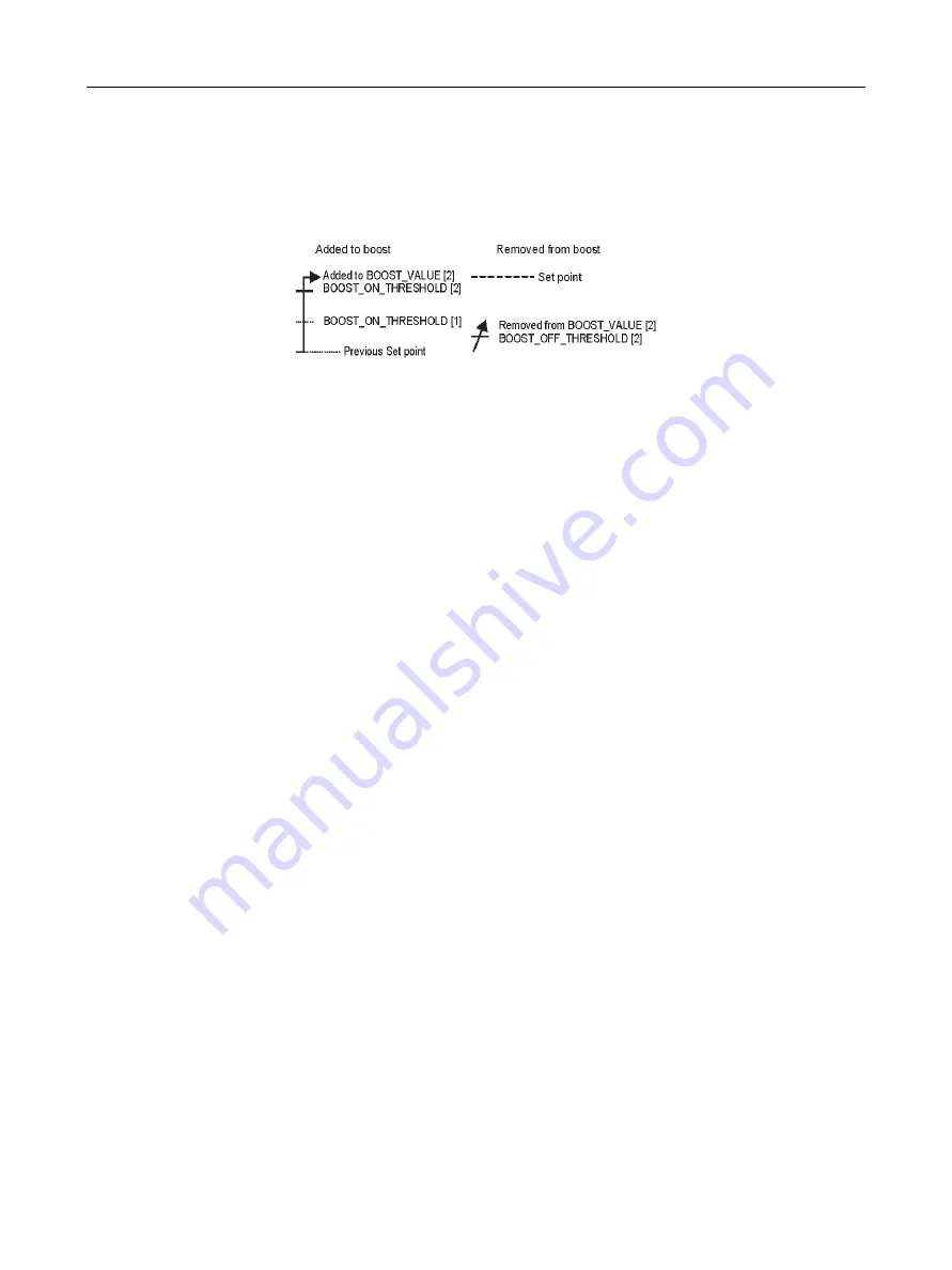
If the difference between the old set point and the new set point is greater than
BOOST_ON_THRESHOLD[2],
BOOST_VALUE[2] functions independently from BOOST_VALUE[1], and the added
value is removed when the deviation enters the range of BOOST_OFF_THRESHOLD[2].
Figure 91
Boost Threshold 1
The boost function of single-acting actuators works only for the air supply side; however,
that of double-acting actuators also works for the exhaust side of OUT1 (for the air
delivery side of OUT2).
If you want to individually set parameters for the exhaust side of OUT1 of double-acting
actuators, set the following parameters.
X_BST_ON_THRESHOLD [1], [2] Tuning range: -10 to 10% (Default: 0, 0%)
X_BST_OFF_THRESHOLD [1], [2] Tuning range: -10 to 10% (Default: 0, 0%)
X_BOOST_VALUE [1], [2] Tuning range: -50 to 50% of MV (Default: 0, 0% of MV)
If you want the boost function of double-acting actuators on the exhaust side of OUT1 to
be asymmetric from the air delivery side, set these parameters. If you set values for these
parameters, input differences for change in relation to the values of
BOOST_ON_THRESHOLD, BOOST_OFF_THRESHOLD, and BOOST_VALUE.
For example, if you want to stop the boost function only on the exhaust side, input a
negative value of the absolute value of BOOST_VALUE[1] in X_BOOST_VALUE[1], and
input the value in X_BOOST_VALUE[2] in the same way to negate the effect. At this time,
you do not need to change the values of X_BST_ON_THRESHOLD and
X_BST_OFF_THRESHOLD.
Theses parameters are valid only for double-acting actuators.
SERVO_I_SLEEP_LMT Tuning range: 0 to 10 sec (Default: 0 sec)
If the deviation changes, the integration operation is stopped for the time of
SERVO_I_SLEEP_LMT to reduce excessive integral components.
If the hysteresis of a valve is large, the valve may not react for a while after an input
change, and a delay in response may occur. This delay in response is accompanied by a
large deviation, and the accumulation of excessive integral components can cause an
overshoot. This parameter is effective in cases such as this.
Summary of Contents for FVP110
Page 14: ...FVP 110 Fieldbus Valve Positioner Manual This page intentionally left blank ...
Page 22: ...FVP 110 Fieldbus Valve Positioner Manual This page intentionally left blank ...
Page 48: ...FVP 110 Fieldbus Valve Positioner Manual This page intentionally left blank ...
Page 50: ...FVP 110 Fieldbus Valve Positioner Manual 34 GE Energy Block Diagram Figure 14 Block Diagram ...
Page 74: ...FVP 110 Fieldbus Valve Positioner Manual This page intentionally left blank ...
Page 88: ...FVP 110 Fieldbus Valve Positioner Manual This page intentionally left blank ...
Page 97: ...81 Dimensions Standard Specifications Dimensions Figure 46 Single Acting Actuator Dimensions ...
Page 99: ...83 Dimensions Standard Specifications Figure 48 Terminal Configuration ...
Page 100: ...FVP 110 Fieldbus Valve Positioner Manual This page intentionally left blank ...
Page 115: ...99 View Object Configuration Table 11 View Object for Transducer Block continued ...
Page 117: ...101 View Object Configuration Table 18 View Object for AO Function Block ...
Page 119: ...103 View Object Configuration Table 20 View Object for OS Function Block ...
Page 121: ...105 View Object Configuration Table 22 View Object for Resource Block ...
Page 124: ...FVP 110 Fieldbus Valve Positioner Manual This page intentionally left blank ...
Page 130: ...FVP 110 Fieldbus Valve Positioner Manual This page intentionally left blank ...
Page 138: ...FVP 110 Fieldbus Valve Positioner Manual This page intentionally left blank ...
Page 156: ...FVP 110 Fieldbus Valve Positioner Manual This page intentionally left blank ...
Page 168: ...FVP 110 Fieldbus Valve Positioner Manual This page intentionally left blank ...
Page 238: ...FVP 110 Fieldbus Valve Positioner Manual 222 GE Energy Table 72 LM Parameter Part List ...
Page 239: ...223 LM Parameter List Link Master Functions ...
Page 246: ...FVP 110 Fieldbus Valve Positioner Manual This page intentionally left blank ...
Page 262: ...FVP 110 Fieldbus Valve Positioner Manual 246 GE Energy Table 85 Download Error Codes ...
Page 265: ...249 Comments on System Network Software Download Table 88 DOMAIN_DESCRIPTOR ...
Page 266: ...FVP 110 Fieldbus Valve Positioner Manual 250 GE Energy Table 89 DOMAIN_HEADER ...
Page 288: ...FVP 110 Fieldbus Valve Positioner Manual This page intentionally left blank ...
Page 289: ...273 H Customer Maintenance Parts List ...
Page 290: ...FVP 110 Fieldbus Valve Positioner Manual 274 GE Energy ...
Page 291: ......


