13
FM Certification
Safety
❑
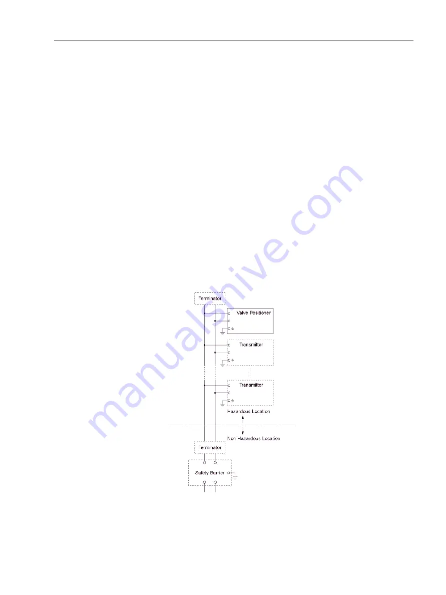
The safety barrier may include a terminator.
❑
More than one field instruments may be connected to the power supply line.
Note 3. Installation
❑
Dust-tight conduit seal must be used when installed in Class II and Class III
environments.
❑
Control equipment connected to the Associated Apparatus must not use or
generate more than 250 Vrms or Vdc.
❑
Installation should be in accordance with ANSI/ISA RP12.6 “Installation of
Intrinsically Safe Systems for Hazardous (Classified) Locations” and the National
Electrical Code (ANSI/NFPA 70) Sections 504 and 505.
❑
The configuration of Associated Apparatus must be Factory Mutual Research
Approved under FISCO Concept.
❑
Associated Apparatus manufacturer’s installation drawing must be followed
when installing this equipment.
❑
The FVP series are approved for Class I, Zone 0, applications. If connecting
AEx[ib] associated Apparatus or AEx ib I.S. Apparatus to the FVP series the I.S.
circuit is only suitable for Class I, Zone 1, or Class I, Zone 2, and is not suitable
for Class I, Zone 0, or Class I, Division 1, Hazardous (Classified) Locations.
Figure 2
Installation Diagram (Intrinsically safe, Division 1 Installation)
Summary of Contents for FVP110
Page 14: ...FVP 110 Fieldbus Valve Positioner Manual This page intentionally left blank ...
Page 22: ...FVP 110 Fieldbus Valve Positioner Manual This page intentionally left blank ...
Page 48: ...FVP 110 Fieldbus Valve Positioner Manual This page intentionally left blank ...
Page 50: ...FVP 110 Fieldbus Valve Positioner Manual 34 GE Energy Block Diagram Figure 14 Block Diagram ...
Page 74: ...FVP 110 Fieldbus Valve Positioner Manual This page intentionally left blank ...
Page 88: ...FVP 110 Fieldbus Valve Positioner Manual This page intentionally left blank ...
Page 97: ...81 Dimensions Standard Specifications Dimensions Figure 46 Single Acting Actuator Dimensions ...
Page 99: ...83 Dimensions Standard Specifications Figure 48 Terminal Configuration ...
Page 100: ...FVP 110 Fieldbus Valve Positioner Manual This page intentionally left blank ...
Page 115: ...99 View Object Configuration Table 11 View Object for Transducer Block continued ...
Page 117: ...101 View Object Configuration Table 18 View Object for AO Function Block ...
Page 119: ...103 View Object Configuration Table 20 View Object for OS Function Block ...
Page 121: ...105 View Object Configuration Table 22 View Object for Resource Block ...
Page 124: ...FVP 110 Fieldbus Valve Positioner Manual This page intentionally left blank ...
Page 130: ...FVP 110 Fieldbus Valve Positioner Manual This page intentionally left blank ...
Page 138: ...FVP 110 Fieldbus Valve Positioner Manual This page intentionally left blank ...
Page 156: ...FVP 110 Fieldbus Valve Positioner Manual This page intentionally left blank ...
Page 168: ...FVP 110 Fieldbus Valve Positioner Manual This page intentionally left blank ...
Page 238: ...FVP 110 Fieldbus Valve Positioner Manual 222 GE Energy Table 72 LM Parameter Part List ...
Page 239: ...223 LM Parameter List Link Master Functions ...
Page 246: ...FVP 110 Fieldbus Valve Positioner Manual This page intentionally left blank ...
Page 262: ...FVP 110 Fieldbus Valve Positioner Manual 246 GE Energy Table 85 Download Error Codes ...
Page 265: ...249 Comments on System Network Software Download Table 88 DOMAIN_DESCRIPTOR ...
Page 266: ...FVP 110 Fieldbus Valve Positioner Manual 250 GE Energy Table 89 DOMAIN_HEADER ...
Page 288: ...FVP 110 Fieldbus Valve Positioner Manual This page intentionally left blank ...
Page 289: ...273 H Customer Maintenance Parts List ...
Page 290: ...FVP 110 Fieldbus Valve Positioner Manual 274 GE Energy ...
Page 291: ......


