FVP 110 Fieldbus Valve Positioner Manual
36
GE Energy
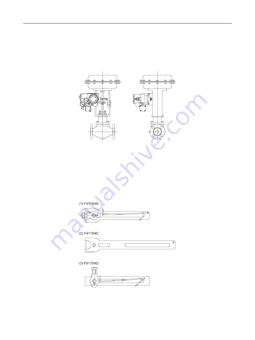
Installing FVP110 on a Linear-motion Control Valve
This section gives the general installation procedure when assembling an FVP110 with a
linear-motion control valve (e.g., a globe valve) combined with a diaphragm actuator or
cylinder actuator (Figure 15). The most suitable procedure may differ depending on the
shapes of the bracket and valve actuator, and the structure of the mounting position.
Figure 15
FVP Installed on Linear-motion Valve/Actuator
1. Attach the bracket to FVP110 using the four M8 bolts supplied (See “Part Names” on
2. Choose the appropriate feed back lever. The FVP110 with option code /LV1 comes
with two different feedback levers, (1) and (2), and the one with option code /LV2
comes with lever (3) (Figure 16). Check the specifications of the levers (Table 1) and
choose the lever most suitable lever by valve.
Figure 16
Feedback Levers
Summary of Contents for FVP110
Page 14: ...FVP 110 Fieldbus Valve Positioner Manual This page intentionally left blank ...
Page 22: ...FVP 110 Fieldbus Valve Positioner Manual This page intentionally left blank ...
Page 48: ...FVP 110 Fieldbus Valve Positioner Manual This page intentionally left blank ...
Page 50: ...FVP 110 Fieldbus Valve Positioner Manual 34 GE Energy Block Diagram Figure 14 Block Diagram ...
Page 74: ...FVP 110 Fieldbus Valve Positioner Manual This page intentionally left blank ...
Page 88: ...FVP 110 Fieldbus Valve Positioner Manual This page intentionally left blank ...
Page 97: ...81 Dimensions Standard Specifications Dimensions Figure 46 Single Acting Actuator Dimensions ...
Page 99: ...83 Dimensions Standard Specifications Figure 48 Terminal Configuration ...
Page 100: ...FVP 110 Fieldbus Valve Positioner Manual This page intentionally left blank ...
Page 115: ...99 View Object Configuration Table 11 View Object for Transducer Block continued ...
Page 117: ...101 View Object Configuration Table 18 View Object for AO Function Block ...
Page 119: ...103 View Object Configuration Table 20 View Object for OS Function Block ...
Page 121: ...105 View Object Configuration Table 22 View Object for Resource Block ...
Page 124: ...FVP 110 Fieldbus Valve Positioner Manual This page intentionally left blank ...
Page 130: ...FVP 110 Fieldbus Valve Positioner Manual This page intentionally left blank ...
Page 138: ...FVP 110 Fieldbus Valve Positioner Manual This page intentionally left blank ...
Page 156: ...FVP 110 Fieldbus Valve Positioner Manual This page intentionally left blank ...
Page 168: ...FVP 110 Fieldbus Valve Positioner Manual This page intentionally left blank ...
Page 238: ...FVP 110 Fieldbus Valve Positioner Manual 222 GE Energy Table 72 LM Parameter Part List ...
Page 239: ...223 LM Parameter List Link Master Functions ...
Page 246: ...FVP 110 Fieldbus Valve Positioner Manual This page intentionally left blank ...
Page 262: ...FVP 110 Fieldbus Valve Positioner Manual 246 GE Energy Table 85 Download Error Codes ...
Page 265: ...249 Comments on System Network Software Download Table 88 DOMAIN_DESCRIPTOR ...
Page 266: ...FVP 110 Fieldbus Valve Positioner Manual 250 GE Energy Table 89 DOMAIN_HEADER ...
Page 288: ...FVP 110 Fieldbus Valve Positioner Manual This page intentionally left blank ...
Page 289: ...273 H Customer Maintenance Parts List ...
Page 290: ...FVP 110 Fieldbus Valve Positioner Manual 274 GE Energy ...
Page 291: ......


