FVP 110 Fieldbus Valve Positioner Manual
68
GE Energy
Periodic Inspections
To maintain problem-free plant operation, periodic inspections are required. At each
periodic inspection, ensure that:
❑
No external damage is seen.
❑
No leakage from the FVP110 or the piping around it is detected.
❑
No build up in the drain, or dust or oil adhering to the air supply line has occurred.
Cleaning the Fixed Nozzle
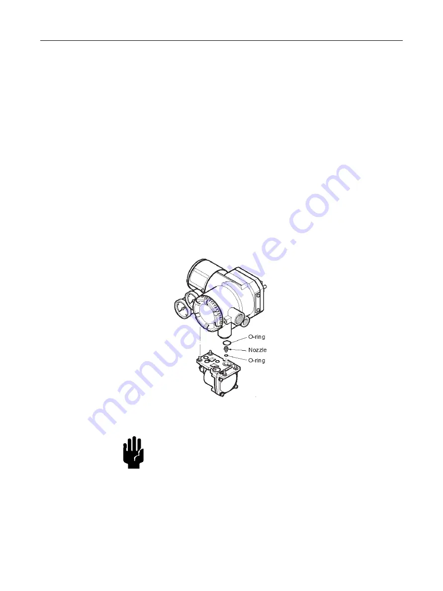
The FVP110 fixed nozzle is attached to the control relay’s surface that engages the
FVP110’s main structure (Figure 40). To clean the fixed nozzle:
1. Detach the control relay from the FVP110 main structure as in “Replacing the Control
2. Thread a wire with a 0.25 mm diameter through the nozzle to clean it.
3. Replace the nozzle and O-ring at the original position and re-attach the control relay.
Figure 40
Cleaning the Nozzle
CAUTION
All the O-rings used for the sealing of pneumatic signal
circuits are made of silicon rubber. The sealing capability is
degraded if general silicon grease is applied. When applying
grease to a sealing part, use a type of grease compatible with
silicon rubber, such as fluoride grease and grease for silicon
rubber.
Summary of Contents for FVP110
Page 14: ...FVP 110 Fieldbus Valve Positioner Manual This page intentionally left blank ...
Page 22: ...FVP 110 Fieldbus Valve Positioner Manual This page intentionally left blank ...
Page 48: ...FVP 110 Fieldbus Valve Positioner Manual This page intentionally left blank ...
Page 50: ...FVP 110 Fieldbus Valve Positioner Manual 34 GE Energy Block Diagram Figure 14 Block Diagram ...
Page 74: ...FVP 110 Fieldbus Valve Positioner Manual This page intentionally left blank ...
Page 88: ...FVP 110 Fieldbus Valve Positioner Manual This page intentionally left blank ...
Page 97: ...81 Dimensions Standard Specifications Dimensions Figure 46 Single Acting Actuator Dimensions ...
Page 99: ...83 Dimensions Standard Specifications Figure 48 Terminal Configuration ...
Page 100: ...FVP 110 Fieldbus Valve Positioner Manual This page intentionally left blank ...
Page 115: ...99 View Object Configuration Table 11 View Object for Transducer Block continued ...
Page 117: ...101 View Object Configuration Table 18 View Object for AO Function Block ...
Page 119: ...103 View Object Configuration Table 20 View Object for OS Function Block ...
Page 121: ...105 View Object Configuration Table 22 View Object for Resource Block ...
Page 124: ...FVP 110 Fieldbus Valve Positioner Manual This page intentionally left blank ...
Page 130: ...FVP 110 Fieldbus Valve Positioner Manual This page intentionally left blank ...
Page 138: ...FVP 110 Fieldbus Valve Positioner Manual This page intentionally left blank ...
Page 156: ...FVP 110 Fieldbus Valve Positioner Manual This page intentionally left blank ...
Page 168: ...FVP 110 Fieldbus Valve Positioner Manual This page intentionally left blank ...
Page 238: ...FVP 110 Fieldbus Valve Positioner Manual 222 GE Energy Table 72 LM Parameter Part List ...
Page 239: ...223 LM Parameter List Link Master Functions ...
Page 246: ...FVP 110 Fieldbus Valve Positioner Manual This page intentionally left blank ...
Page 262: ...FVP 110 Fieldbus Valve Positioner Manual 246 GE Energy Table 85 Download Error Codes ...
Page 265: ...249 Comments on System Network Software Download Table 88 DOMAIN_DESCRIPTOR ...
Page 266: ...FVP 110 Fieldbus Valve Positioner Manual 250 GE Energy Table 89 DOMAIN_HEADER ...
Page 288: ...FVP 110 Fieldbus Valve Positioner Manual This page intentionally left blank ...
Page 289: ...273 H Customer Maintenance Parts List ...
Page 290: ...FVP 110 Fieldbus Valve Positioner Manual 274 GE Energy ...
Page 291: ......


