22
GE INFORMATION
G500 SUBSTATION GATEWAY INSTRUCTION MANUAL
CHAPTER 3: INSTALLING THE G500
–
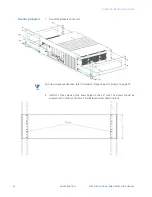
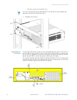
M6x0.5 screws use 33.3 in-lb [3.76 Nm]
NOTE
It is not recommended to ship the G500 installed in a rack without support brackets and
adequate conductive foam blocking in place.
5.
Install the 4 other screws.
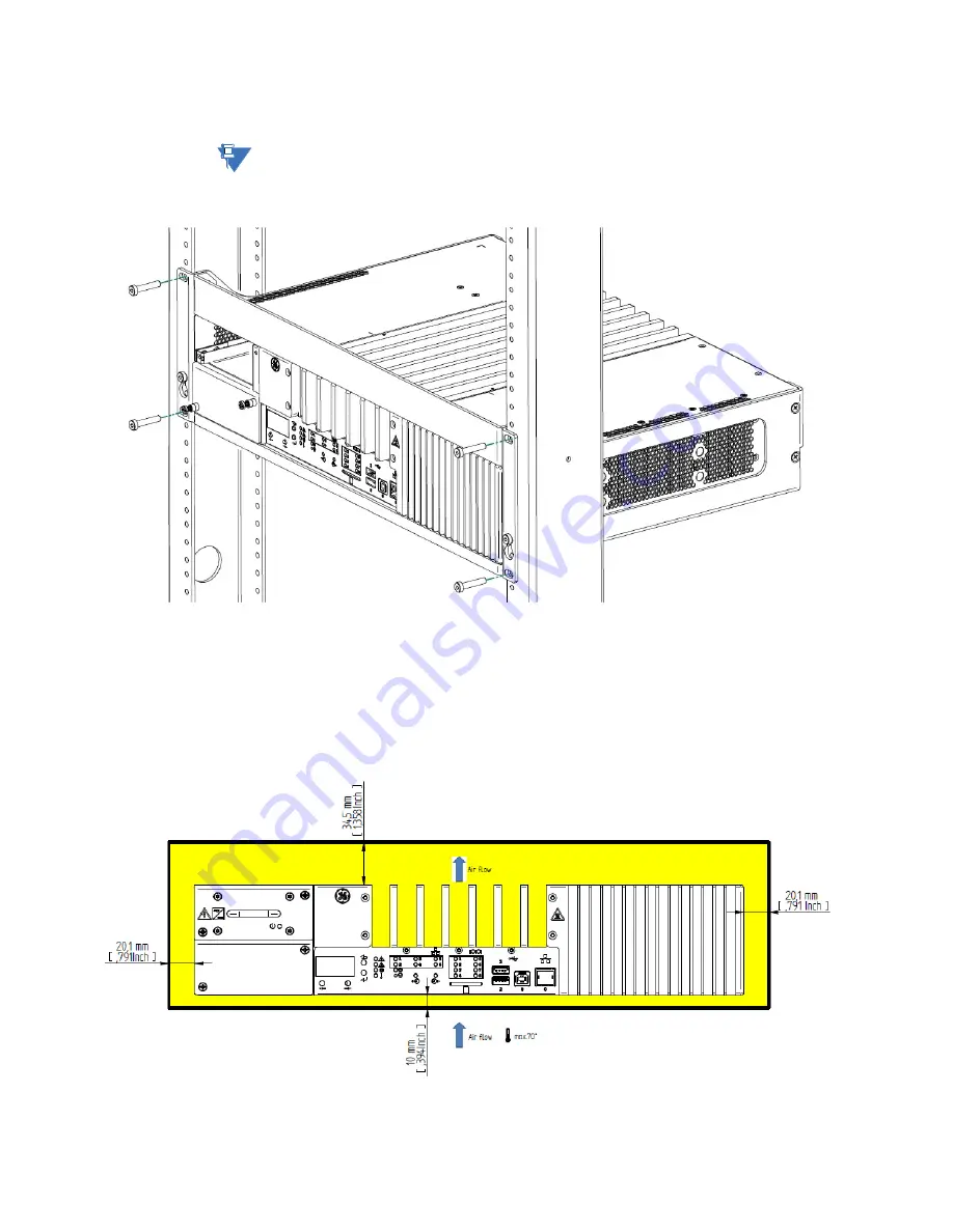
Spacing for air
circulation
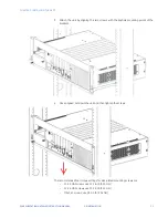
To guarantee sufficient air circulation, the specified spacing above, below, to the sides, in
front and behind the G500 must be met or exceeded. The thermal impact on devices next
to each other is negligible (1°C) with the mounting spaces below, assuming the adjacent
devices are also G500s or devices dissipating a similar amount of power.
The minimum specified spacing to the front and behind the G500 is 5cm (2”). Other spacing
requirements are indicated in the following diagram. These requirements are met when
the G500 is installed using the provided rack mounting kit.
Summary of Contents for G500
Page 6: ...6 GE INFORMATION G500 SUBSTATION GATEWAY INSTRUCTION MANUAL TABLE OF CONTENTS ...
Page 16: ...16 GE INFORMATION G500 SUBSTATION GATEWAY INSTRUCTION MANUAL CHAPTER 1 INTRODUCTION ...
Page 36: ...36 GE INFORMATION G500 SUBSTATION GATEWAY INSTRUCTION MANUAL CHAPTER 3 INSTALLING THE G500 ...
Page 64: ...64 GE INFORMATION G500 SUBSTATION GATEWAY INSTRUCTION MANUAL CHAPTER 4 INTERFACES ...
Page 72: ...72 GE INFORMATION G500 SUBSTATION GATEWAY INSTRUCTION MANUAL CHAPTER 5 INDICATORS ...
Page 77: ...CHAPTER 6 SPECIFICATIONS G500 SUBSTATION GATEWAY INSTRUCTION MANUAL GE INFORMATION 77 ...
Page 78: ...78 GE INFORMATION G500 SUBSTATION GATEWAY INSTRUCTION MANUAL CHAPTER 6 SPECIFICATIONS ...
Page 80: ...80 GE INFORMATION G500 SUBSTATION GATEWAY INSTRUCTION MANUAL CHAPTER 6 SPECIFICATIONS ...
Page 86: ...86 GE INFORMATION G500 SUBSTATION GATEWAY INSTRUCTION MANUAL APPENDIX B CUL ...
Page 88: ...88 GE INFORMATION G500 SUBSTATION GATEWAY INSTRUCTION MANUAL APPENDIX C WARRANTY ...
Page 92: ...92 GE INFORMATION G500 SUBSTATION GATEWAY INSTRUCTION MANUAL REVISION HISTORY ...

