42
GE INFORMATION
G500 SUBSTATION GATEWAY INSTRUCTION MANUAL
CHAPTER 4: INTERFACES
NOTE
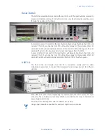
The Multi-Stream Transport (MST) feature in Display Port, for daisy-chaining monitors, is
supported only for the Windows Operating System.
Each display port is fused separately. For normal operation don’t exceed 0.5 A per
connector. The cumulative current draw of the two ports is limited to 0.5A due to Thermal
and power budget restrictions.
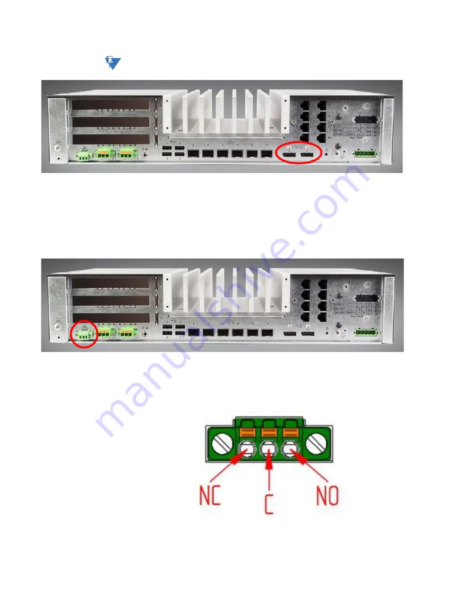
Alarm
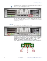
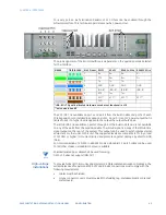
At the rear of the unit an Alarm output connector is located.
This connector has three contacts NO, C and NC. This are the contacts of a solid state relay
controlled by the watchdog and software.
The relay voltage should be Limited to switching
up to 48VAC or 75VDC with maximum 100mA to comply with IEC 61850-3. If 61850-3
Compliance is not required, the relay may switch up to 300VAC or 300VDC.
This Port is isolated from the rest of system in accordance to IEC60950 for use with mains.
Summary of Contents for G500
Page 6: ...6 GE INFORMATION G500 SUBSTATION GATEWAY INSTRUCTION MANUAL TABLE OF CONTENTS ...
Page 16: ...16 GE INFORMATION G500 SUBSTATION GATEWAY INSTRUCTION MANUAL CHAPTER 1 INTRODUCTION ...
Page 36: ...36 GE INFORMATION G500 SUBSTATION GATEWAY INSTRUCTION MANUAL CHAPTER 3 INSTALLING THE G500 ...
Page 64: ...64 GE INFORMATION G500 SUBSTATION GATEWAY INSTRUCTION MANUAL CHAPTER 4 INTERFACES ...
Page 72: ...72 GE INFORMATION G500 SUBSTATION GATEWAY INSTRUCTION MANUAL CHAPTER 5 INDICATORS ...
Page 77: ...CHAPTER 6 SPECIFICATIONS G500 SUBSTATION GATEWAY INSTRUCTION MANUAL GE INFORMATION 77 ...
Page 78: ...78 GE INFORMATION G500 SUBSTATION GATEWAY INSTRUCTION MANUAL CHAPTER 6 SPECIFICATIONS ...
Page 80: ...80 GE INFORMATION G500 SUBSTATION GATEWAY INSTRUCTION MANUAL CHAPTER 6 SPECIFICATIONS ...
Page 86: ...86 GE INFORMATION G500 SUBSTATION GATEWAY INSTRUCTION MANUAL APPENDIX B CUL ...
Page 88: ...88 GE INFORMATION G500 SUBSTATION GATEWAY INSTRUCTION MANUAL APPENDIX C WARRANTY ...
Page 92: ...92 GE INFORMATION G500 SUBSTATION GATEWAY INSTRUCTION MANUAL REVISION HISTORY ...

