5.2 BACKUP BATTERY SWITCH
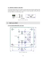
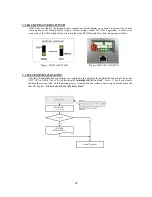
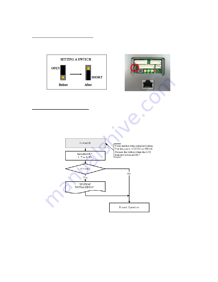
GE314 has a switch for the backup battery connection, which remains open circuit to prevent any current
consumption of the backup battery (Figure: Switch setting). Before the GE314 operation, it needs to be
connected so that the backup battery can retain the serial RTC(Date and Time data) during power failure.
Fi
gure: SWITCH SETTING
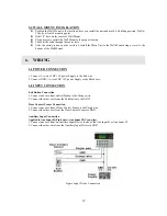
Fi
gure: SWITCH LOCATION
5.3 SYSTEM INITIALIZATION
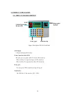
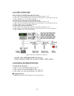
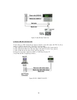
After the all installation and connections are completed, press and hold the Initialize button and put the power
(+12V DC) to GE314. The LCD will first display “
Initialize OK? 0:No 1:Yes”
. Press <1> key if you want to
initialize the system. After all Initialization process is completed, the system is operating on normal mode and
the LCD displays “
GE Security, GE314 [F1], Date Time
”.
16
Summary of Contents for GE314
Page 1: ...OPERATING MANUAL FINGERPRINT ACCESS CONTROLLER MODEL GE314 ...
Page 33: ...9 2 F2 SETUP MENU 33 ...
Page 37: ...9 3 F3 SETUP MENU 37 ...
Page 42: ...9 4 F4 SETUP MENU 9 4 1 ID REGISTRATION 1 Registration by RF Card 42 ...
Page 47: ...9 5 F5 SETUP MENU 9 5 1 TIME SCHEDULE 47 ...
Page 50: ...9 6 F6 SETUP MENU 50 ...
Page 53: ...9 7 F7 SETUP MENU 53 ...
Page 71: ...A S REQUEST FORM ORIGINAL 71 ...
Page 72: ...A S REQUEST FORM SAMPLE 72 ...
Page 73: ...MEMO 73 ...

