1.
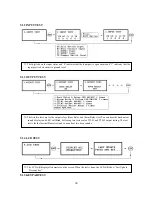
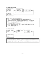
Scanning…
The reader is waiting for the ID number to be registered. The card number will appear with a
beep sound when you present the card. ID number is 8digit number.
2.
ID:
ID number consists of 4~8 digit. Enter 4~8digit ID number (PIN) and press <
ENT
> key on the field.
3.
PW:
PW is the password which can be used to access the doors with RF + Password operating mode. It is
necessary to enter a default password (‘
0000
’) when you register an ID.
4.
TA:
TA is the Time Schedule code (‘
00
’ ~ ‘
10
’) for the Reader#1 (Built-in Reader). When you present the
card to the Reader#1, the cardholder is only allowed the access of the door during the Time intervals of the
Time Schedule code entered to TA. To setup the Time intervals for each Time Schedule code, refer to the
ard to the Reader#2, the cardholder is only allowed the access of the door during the Time intervals of the
the door anytime for the cardholder
en enter the default Time Schedule code '00' for the value.
n
ns
ss Door Error”) on the LCD display.
A,
‘3’ – ID + Pa Finger Mode
‘1’ – ID Only Mode
Time Schedule Setup on the [
F5 SETUP MENU
]. If you want to access the door anytime for the cardholder
then enter the default Time Schedule code '00' for the value.
5.
TB:
TB is the Time Schedule code (‘
00
’ ~ ‘
10
’) for the Reader#2 (Exit Reader). When you present the
c
Time Schedule code entered to TB. To setup the Time intervals for each Time Schedule code, refer to the
Time Schedule Setup on the [
F5 SETUP MENU
]. If you want to access
th
6.
RD
: RD is the Reader Assignment code for the cardholder. Code ‘0’ assigns for both readers (Built-i
Reader and Exit Reader), code ‘1’ only assigns Reader#1 (Built-in Reader) and code ‘2’ only assig
Reader#2 (Exit Reader). If you put ‘1’ for RD (Only Reader#1 assigned) and try to exit through Reader#2
(Exit Reader) then GE314 generates an error message (“Acce
7.
MA
: MA is the Reader#1 (Built-in Reader) Operating Mode for the cardholder. If you put ‘1’ for M
Reader#1 is always operating on RF Only Mode.
‘0’ – System Operating Mode [
F2 SETUP MENU
] [
READER#1 MODE
]
‘1’ – ID Only Mode
‘2’ – ID + Finger(Password) Mode
8.
MB
: MB is the Reader#2 (Exit Reader) Operating Mode for the cardholder. If you put ‘1’ for MB,
Reader#2 is always operating on RF Only Mode.
‘0’ – System Operating Mode [
F2 SETUP MENU
] [
READER#2 MODE
]
‘2’ – ID + Password Mode
25
Summary of Contents for GE314
Page 1: ...OPERATING MANUAL FINGERPRINT ACCESS CONTROLLER MODEL GE314 ...
Page 33: ...9 2 F2 SETUP MENU 33 ...
Page 37: ...9 3 F3 SETUP MENU 37 ...
Page 42: ...9 4 F4 SETUP MENU 9 4 1 ID REGISTRATION 1 Registration by RF Card 42 ...
Page 47: ...9 5 F5 SETUP MENU 9 5 1 TIME SCHEDULE 47 ...
Page 50: ...9 6 F6 SETUP MENU 50 ...
Page 53: ...9 7 F7 SETUP MENU 53 ...
Page 71: ...A S REQUEST FORM ORIGINAL 71 ...
Page 72: ...A S REQUEST FORM SAMPLE 72 ...
Page 73: ...MEMO 73 ...


