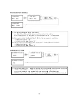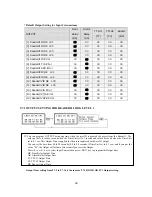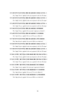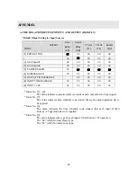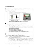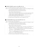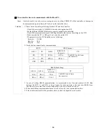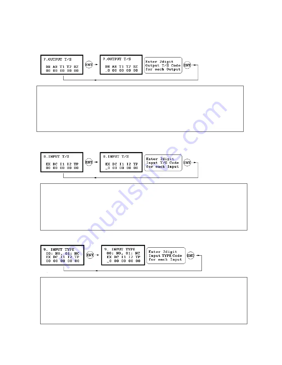
9.6.7 OUTPUT TIME SCHEDULE SETTING
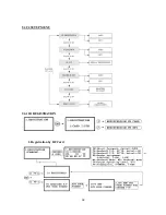
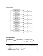
9.6.8 INPUT TIME SCHEDULE SETTING
.6.9 I
NG
Outputs. This setting i
to o
me I
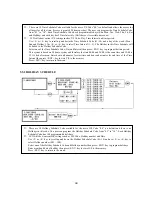
Press <ENT> key to l
AR: Alarm Relay Output T
T1: TTL#1 Output T/S Cod
TTL#2 Output T/S Code
BZ: Buzzer Output T/S Code
. You can
☞
link a T/S Code to each Output. The default T/S Code is “00” which means no T/S is applied to the
s very useful when you want
pen the door for a Ti
nterval.
ink a T/S Code to the Output then enter 2digit T/S Code for each Output.
DR: Door Relay Output T/S Code
/S Code
e
T2:
NPUT TYPE SETTI
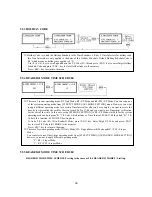
DC: Door Contact Sensor Input T/S Code
I1: Aux Input#1 T/S Code
I2: Aux Input#2 T/S Code
TP: Tamper Switch Input T/S Code
. You can
☞
link a T/S Code to each Input. The default T/S Code is “00” which means no T/S is applied to the
Inputs. This setting is very useful when you want to activate PIR sensor input for a Time Interval.
Press <ENT> key to link a T/S Code to the Input then enter 2digit T/S Code for each Input.
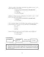
EX: EXIT Button Input T/S Code
9
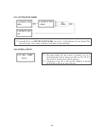
EX: EXIT Button Input type
DC: Door Contact Sensor Input type
I1: Aux Input#1 type
. You can
☞
program input type(00: NO, 01: NC) to each Input. The default input type is “00” which means input
is NO type.
Press <ENT> key then enter 2digit Code for each Input.
I2: Aux Input#2 type
TP: Tamper Switch is “00” because it is internal device.
52
Summary of Contents for GE314
Page 1: ...OPERATING MANUAL FINGERPRINT ACCESS CONTROLLER MODEL GE314 ...
Page 33: ...9 2 F2 SETUP MENU 33 ...
Page 37: ...9 3 F3 SETUP MENU 37 ...
Page 42: ...9 4 F4 SETUP MENU 9 4 1 ID REGISTRATION 1 Registration by RF Card 42 ...
Page 47: ...9 5 F5 SETUP MENU 9 5 1 TIME SCHEDULE 47 ...
Page 50: ...9 6 F6 SETUP MENU 50 ...
Page 53: ...9 7 F7 SETUP MENU 53 ...
Page 71: ...A S REQUEST FORM ORIGINAL 71 ...
Page 72: ...A S REQUEST FORM SAMPLE 72 ...
Page 73: ...MEMO 73 ...


