☞
The controller does not communicate with the Host-PC.
Cause A defective cable is used, errors in wiring, an error in setting COMM ID of the controller, or damage on
the communication port (either on PC side or on the controller side).
1. Please check the settings of the application S/W and the controller.
- Check if the controller’s COMM ID is listed on the application S/W.
ntrollers are installed
- Set the different COMM ID when two or more co
- Check if the communication speed (9600bps def
- Make sure that the PC’s COM port is set correctly on the S/W.
- The parameters at the S/W should be set as following:
Parity bit : NONE
Data bit : 8bit
Stop bit : 1bit
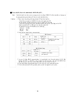
2. Check the line connection for communication.
RS232 RS485
(mono)
Solution
.
ault) is the same as the setting on the S/W.
GE313 PC GE314
RS485/232
Converter
PC
RX
TX
RTX(-)
RTX(-)
TX RX
RTX(+)
RTX(+)
GND GND
The RS232 cable from
the converter
RS485(Multi Drop)
GE314
GE314
RS485/232
Converter
PC
RX(-) RX(-)
TX(-)
RX(+) RX(+)
TX(+)
The RS232 cable from
the converter
3. In case of setting RS485 communication, we recommend to use line-end resistors of 120 Ohm
between the RTX (+) and RTX (-) lines. Apply the same resistors to the converter RS485 lines.
Consult a service center or an electric technician if you are no
4. When a multi-drop communication doesn’t work, test one
5. If the trouble remains after the procedure above, contact a
t sure how to do it.
-by-one communication first.
designated service center.
66
Summary of Contents for GE314
Page 1: ...OPERATING MANUAL FINGERPRINT ACCESS CONTROLLER MODEL GE314 ...
Page 33: ...9 2 F2 SETUP MENU 33 ...
Page 37: ...9 3 F3 SETUP MENU 37 ...
Page 42: ...9 4 F4 SETUP MENU 9 4 1 ID REGISTRATION 1 Registration by RF Card 42 ...
Page 47: ...9 5 F5 SETUP MENU 9 5 1 TIME SCHEDULE 47 ...
Page 50: ...9 6 F6 SETUP MENU 50 ...
Page 53: ...9 7 F7 SETUP MENU 53 ...
Page 71: ...A S REQUEST FORM ORIGINAL 71 ...
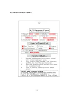
Page 72: ...A S REQUEST FORM SAMPLE 72 ...
Page 73: ...MEMO 73 ...


