background image


1 of 11 

© 2010 GE Security, Inc. 

P/N 1069686 • REV 1.0 • ISS 10MAR10 

GE 
Security 

Multi-Channel VPD Combiner 

Receiver Installation Sheet 

Introduction 

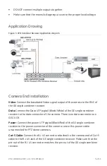
GE Security Multi-Channel Video Power Data Combiner Receivers combine video, 
PTZ data, and camera power over a single 4-pair UTP cable to simplify CCTV 
installations in a structured wiring environment. They support up to 16 cameras 
and should be installed in the control room. 

The GEC-4VDPBC and GEC-16VDPBC need to be used along with external class II 
power supplies. The GEC-8PVPDTCHUB and GEC-16PVPDTCHUB come with built-
in 8 and 16 channel fully isolated class II 24/28 VAC power supplies. Each camera 
power output in addition to an auto-reset fuse is equipped with a 2 A glass fuse 
that is easily accessible from the front panel.  

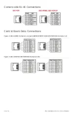
At the camera end a video balun/combiner provides video, power and data on 
separate outputs. The video connections are through BNC connectors to the DVR 
or matrix switches.  The data connections to the DVR are through RJ-45 
connectors.  There is a separate data connection for each camera.  All equipment 
follows industry-standard EIA/TIA 568B pin-outs. 

The following model numbers are covered in this document: 

• GEC-4VDPBC 

• GEC-16VDPBC 

• GEC-8PVPDTCHUB 

• GEC-16PVPDTCHUB


Summary of Contents for GEC-4VDPBC

Page 1: ...8PVPDTCHUB and GEC 16PVPDTCHUB come with built in 8 and 16 channel fully isolated class II 24 28 VAC power supplies Each camera power output in addition to an auto reset fuse is equipped with a 2 A g...

Page 2: ...s been damaged in any way such as a power supply cord or plug is damaged liquid has been spilled or objects have fallen into the apparatus the apparatus has been exposed to rain or moisture does not o...

Page 3: ...vers Passive GE transceivers can transmit video and Up the Coax P T Z control signals up to 750 ft 228 m We recommend using short 18 AWG solid wires for ground connections GE VPD products follow the E...

Page 4: ...ation should be made by a qualified service person and should conform to all local codes DO NOT bundle UTP signals in the same conduit as high voltage wiring To reduce the risk of fire or electrical s...

Page 5: ...onnect the Data UTP pigtail Black White of the GE single combiner receiver to the data connector of the camera There is no data connection on GEC VCR Power Connect the power UTP pigtail Black Red of t...

Page 6: ...eiver unit Video Use provided 2 ft 60 cm coax patch cords to connect the BNC video inputs of video receiving devices such as DVRs or matrix switches Data Connect each RJ 45 data connector to a Cat 5 c...

Page 7: ...id span location closer to the cameras Use an active receiver hub at control room Step 3 Use a single channel GE combiner transceiver on the camera side considering the camera voltage Diagnostic LEDs...

Page 8: ...lt Protection 2 A 5x20 mm type T fuse front access plus a 2 5 A self resetting fuse at per channel Main fuse 4 A at 115 VAC 3 A at 220 VAC 5x20 mm GEC 8PVPDTCHUB 7 A at 115 VAC 5 A at 220 VAC 5x20 mm...

Page 9: ...oncondensing Temperature Operating 10 to 50 C Storage 30 to 70 C Specifications are subject to change without notice Included Accessories Mounting brackets for front rear or wall installations Rubber...

Page 10: ...1069686 REV 1 0 ISS 10MAR10 Camera side RJ 45 Connections Control Room Data Connections Figure 2 GEC 4VDPBC Cameras 1 4 only 16VDPBC 8PVPDTCHUB 16PVPDTCHUB Cameras 1 8 Figure 3 GEC 16VDPBC 16PVPDTCHUB...

Page 11: ...owever there is no guarantee that interference will not occur in a particular installation If this equipment does cause harmful interference to radio or television reception which can be determined by...

Reviews: