background image


1 of 9 

© 2010 GE Security, Inc. 

P/N 1069682 • REV 1.0 • ISS 14APR10 

GE 
Security 

Multi-Channel Passive 

Transceiver Hubs Installation 

Sheet 

Introduction 

GE Security Multi-Channel Passive Transceiver Hubs transmit or receive base-
band video signals over unshielded twisted pair (UTP) wires, point-to-point, for 
distances up to 750 feet (228 m).  They also provide support for the “up the coax” 
Pan/Tilt/Zoom (PTZ) control signals. 

These passive hubs are 1U in height and can be wall, desk or rack mounted.  
They use Category 2-7 twisted pair wires and do not require power.  They provide 
built-in surge suppression to protect video equipment against damaging voltage 
spikes and provide noise immunity to ensure quality images.  

The included RJ-45 adapter provides an easy way to connect the passive hubs to 
other GE VPD products via Cat-5 cables and RJ-45 connectors. These passive 
hubs are bidirectional and support Up-the-Coax Pan/Tilt/Zoom telemetry signals. 
Any unused pair of UTP cables can also be used for transporting other telemetry 
signals. 

The following model numbers are covered in this document: 

• GEC-4VPHUB 

• GEC-8VPHUB 


• GEC-16VPHUB 

• GEC-32VPHUB


Summary of Contents for GEC-4VPHUB

Page 1: ...esk or rack mounted They use Category 2 7 twisted pair wires and do not require power They provide built in surge suppression to protect video equipment against damaging voltage spikes and provide noi...

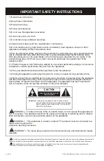
Page 2: ...s been damaged in any way such as a power supply cord or plug is damaged liquid has been spilled or objects have fallen into the apparatus the apparatus has been exposed to rain or moisture does not o...

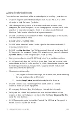
Page 3: ...vers Passive GE transceivers can transmit video and Up the Coax P T Z control signals up to 750 ft 228 m We recommend using short 18 AWG solid wires for ground connections GE VPD products follow the E...

Page 4: ...ft 14 m 90 ft 28 m 240 ft 73 m 1 AMP Camera Dual 23 AWG 58 ft 18 m 114 ft 35 m 300 ft 92 m Important Safety Warnings Installation should be made by a qualified service person and should conform to all...

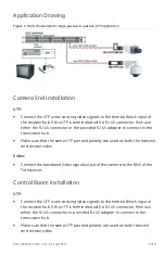
Page 5: ...nect to the transceiver hub Make sure that the same UTP pair and polarity are used on both the transmit and receive sides Video Connect the baseband Video signal output of the camera to the BNC of the...

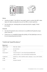
Page 6: ...connector to a qualified earth ground using a short thick wire If the picture is scrambled change the polarity of the twisted pair wires on the corresponding terminal block Technical Specifications E...

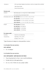
Page 7: ...16VPHUB 17 x 1 74 x 3 in 43 x 4 2 x 7 6 cm GEC 32VPHUB 17 x 1 74 x 3 in 43 x 4 2 x 7 6 cm Weight GEC 4VPHUB 0 2 lb 90 g GEC 8VPHUB 3 3 lb 1500 g GEC 16VPHUB 3 3 lb 1500 g GEC 32VPHUB 3 3 lb 1500 g Env...

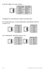
Page 8: ...9 P N 1069682 REV 1 0 ISS 14APR10 EIA TIA 568A B Color Codes Midspan Control Room Data Connections GEC 4VPHUB Cameras 1 4 GEC 8VPHUB GEC 16VPHUB GEC 32VPHUB Cameras 1 8 GEC 16VPHUB GEC 32VPHUB Cameras...

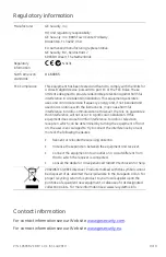
Page 9: ...interference will not occur in a particular installation If this equipment does cause harmful interference to radio or television reception which can be determined by turning the equipment off and on...

Reviews: