background image

GEH-5304A

44

……………………………………………….…………………Fold here and close with staple or tape………………………………….………………….

Place

Stamp

Here

GE INDUSTRIAL SYSTEMS
INDUSTRIAL ENGINEERING TECHNICAL
PUBLICATIONS EDITOR
2000 TAYLOR STREET
FORT WAYNE   IN   46801-2205   USA

…………………………………………………..………….………………..Fold here first……………………………………………………………….

Summary of Contents for GEH-5304A

Page 1: ...GEH 5304A GE Industrial Systems Instructions Direct Current Motors Generators Type CD Frames 2512AT 2513AT Frames 2812AT 2813AT ...

Page 2: ...ble contingency to be met in connection with installation operation or maintenance Should further information be desired or should particular problems arise which are not covered sufficiently for the purchaser s purposes the matter should be referred to the General Electric Company Copyright 1985 1992 1999 General Electric Company ...

Page 3: ...rives 11 Thrust Loads 11 Operation 11 Inspection Before Starting 12 Bearings and Couplings 12 Commutator and Brushes 12 Rectified Power Supplies 12 Power Supply Identificaiton 14 Connections 15 Protective Devices 15 Motor Field Heating 15 Thermostats 15 Speed Limit Device 16 Space Heater 16 Ventilation System 17 General Mechanical Inspection 17 Accessory Mounting 18 Brakes 18 Inspection After Star...

Page 4: ... 25 Shaft End Play 25 Waterproof Machines 25 Lubrication of Flexible Couplings 25 Insulation 25 Testing Methods 26 Visual Inspection 26 Insulation Resistance Measurement 26 Cleaning of Windings 27 Oily Dirt 28 Drying of Windings 29 Service Shop Cleaning 29 Repair 29 Renewal Parts 30 Storage of Renewal Parts 30 Commutator Check Chart 32 ...

Page 5: ...g coverings are NOT suitable for out of doors or unprotected storage Each shipment should be carefully examined upon arrival Any damage should be reported promptly to the carrier and to the nearest office of GE Industrial Systems A Storage During installation or when in storage the machine and its parts must be protected from the following 1 Dirt of all kinds 2 Wetness and temperature extremes Pro...

Page 6: ...must be exercised in removing rust on shaft extensions near shaft seals since it is difficult and sometimes impossible to remove rust from these surfaces without damaging or deforming them Burrs or bumps on other machined surfaces should be carefully removed by using a fine file or scraper Machines in storage should be inspected have the insulation resistance checked at frequent and regular in ter...

Page 7: ...de quate supply of clean dry room air is required for self ventilated separately ventilated and blown motors Where motors must operate in dirty wet or contaminated environments protection in the form of filters or totally enclosed construction must be used to obtain long life with normal maintenance Do not obstruct ventilating openings When filters are supplied service them regularly Dirty filters...

Page 8: ...n reduced downtime 1 Coupled Drive When a motor is used to drive a unit flexible couplings must be used to facilitate alignment Three bearing construction requires a rigid coupling Careful alignment of machines when using either solid rigid or flexible cou plings is essential to prevent excessive vibration and bearing or shaft failures D OLJQPHQW 3URFHGXUH OH LEOH RXSOLQJ 1RQ 6HOI 6XSSRUWLQJ DVHV ...

Page 9: ...lly If the grout is to be prepared at the site a cement sand ratio of 1 2 is recommended No more than enough water should be used to give a stiff mixture The clean but rough surface of the foundations should be wet and the grout forced or puddled under the base 3 V Belt Drives The V belt system produces a heavy shaft and bearing loading making it necessary that these factors be considered carefull...

Page 10: ...multiplying by the bearing life factor It is important to know that bearing life for V belt applications is independent of the motor load Once the belts have been tightened just enough to prevent slipping when the maximum torque is being delivered by the motor the radial load W on the shaft and bearing is there and remains constant re gardless of whether the motor is even turning For timing belts ...

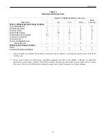
Page 11: ...ounting position These apply to ball bearings only For applications combining thrust and radial loads or where thrust loads exceed the values shown in Table 2 refer all details to GE Industrial Systems Table 2 Maximum Continuous Thrust Capacity Lbs Vertical Mounting Bearing Horizontal Thrust Load Thrust Load Frame Size Mounting Up Down 2512 Std 309 350 465 235 2512 O S 310 400 515 285 2513 Std 309...

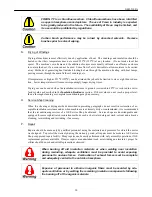
Page 12: ...hould be down and latched Brush pigtail connections should be tight and the pigtails should not interfere with the action of the spring or brush and should be clear of any other part of the machine B Rectified Power Supplies When DC motors are operated from rectified power supplies the pulsating voltage and current wave forms affect the motor performance by increasing motor heating and degrading c...

Page 13: ...scription Shaft Shaft Curve Bearing Diameter Material 1 Standard Ball 309 Standard 1 5 8 Standard 2 Oversize Ball 310 Oversize 1 7 8 Standard 3 Oversize Roller 310 Oversize 1 7 8 Special Frame Sizes CD2512AT and CD2513AT Frame Sizes CD2812AT and CD2813AT Description Shaft Shaft Curve Bearing Diameter Material 1 Standard Ball 310 Standard 1 7 8 Standard 2 Oversize Ball 311 Oversize 2 1 8 Standard 3...

Page 14: ...volt DC motor rat ings and 460 volts for 500 or 550 volt DC motor ratings c Power Supply Identification Letter D This designates a three phase 60 hertz input semi bridge power supply having three controlled pulses per cycle The supply has free wheeling with no series inductance added ex ternally to the motor armature circuit The input line to line AC voltage to the rectifier shall be 230 volts for...

Page 15: ...ding connectors covers and other safety devices are properly attached F Motor Field Heating MOTOR FIELD HOUSING Unless specifically ordered motors are NOT capable of continuous standstill excitation at rated field current When the motor is shut down for more than 30 minutes one of the following options must be used 1 De energize the fields completely 2 Use field economy relays to limit the field c...

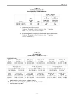
Page 16: ... listed in Table 5 A speed limit device is furnished on machines only when ordered The contacts of the speed limit device automatically reclose after the speed has fallen below the trip value In order to prevent property damage or injury to personnel the control circuit should be designed to prevent re energizing the motor until the cause of the overspeed has been corrected Table 6 Lead Markers Fu...

Page 17: ... And Air Flow K General Mechanical Inspection Check the inside of the machine for tools metal chips or any other foreign material that may have accumu lated during storage or installation Make sure that all rotating parts have clearance from any stationary parts Turn the machine over by hand if possible and check for scraping noises or any other sign of me chanical interference Check the tightness...

Page 18: ...ed separately M Brakes Flange mounted brakes may be mounted on the accessory rabbet Since the accessory stub shaft is not suit able for use with a brake the standard NEMA commutator end shaft extension should be ordered when such use is planned Standard brakes are designed for horizontal floor mounting only When motors are sidewall or ceiling mounted the brake must be reassembled to maintain its r...

Page 19: ...r a short time an inspection should be made to ascertain that there have been no changes since installation Check for increased vibration signs of change in alignment or foundation settling bolts that may have loosened rubbing parts loose connections and worsened commutation Proper steps must be taken to correct the trouble Also check the condition of air filters on blower ventilated machines The ...

Page 20: ...nternal fan remove four 4 3 8 through studs from the commutator end 11 Remove DE bracket 12 Pull armature out from drive end B Reassembly The following procedure should be used for reassembly 1 Place armature into frame 2 Install DE bearing bracket and bearing cap 3 Install the four 4 3 8 through studs into DE bracket 4 Install CE bearing bracket and bearing cap 5 Loosely tighten four 4 nuts on th...

Page 21: ...n removed a bearing puller may be used to pull the bearings from the shaft Protect the shaft center while using the puller Discard the old bearing The new bearing and all mating parts should be kept extremely clean during reassembly To install a new bearing heat the bearing to 116 127 C 240 260 F in oil or in an oven then slip or press the bearing on the shaft The bearing should be mounted tightly...

Page 22: ...D6A2C13 Standard Oil Company Chevron SRI II 20 F to 350 F 225 Bush Street 28 C to 176 C San Francisco CA 94120 415 894 7700 E Brushes Refer to Figure 2 High voltage and rotating machinery can cause serious or fatal injury Brushes may not be touched or replaced while the machine is energized or rotating DC motors and generators operated for long periods of time at light loads or in contaminated atm...

Page 23: ...ushes This can be accomplished by cleaning the dust from the commutator brushholders and adja cent parts with a vacuum cleaner air blast or other suitable means After the rough sanding the brushes should be finely ground to fit using a brush seater Rotate motor at around nameplate RPM Make sure there is no load on the machine armature current is nil Carefully and lightly rub the brush seater acros...

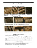
Page 24: ...s give advance warning of deterioration of the commuta tor surface Refer to the Commutator Check Chart GEA 7053 for commutator surface marking and causes of poor commutator condition Commutator runout over 003 T I R Total Indicator Reading and bar to bar readings over 003 indicate need for repair Refer to Table 12 The presence of silicone in DC motors particularly with totally enclosed con structi...

Page 25: ...n a small machine to a large machine may have two different size coupling halves joined by an adapter plate Couplings of this type have a separate lubricant supply for each half Therefore both halves must be lubricated separately K Insulation Eliminate sources of contamination and moisture for maximum insulation life Air filters for blowers air piped from cleaner locations shielding from water lea...

Page 26: ...GEH 5304A 26 ues ...

Page 27: ...e ment for future visual inspections 2 Insulation Resistance Measurement A method of measuring the insulation resistance is described in Report 43 Recommended Practice for Testing Insulation Resistance of Rotating Machinery published by IEEE 345 E 47th Street New York NY 10017 The resistance measurements should be taken with a 500 or 1000 volt megger and corrected to 104 F 40 C The insulation resi...

Page 28: ...ch have been in use If such a test is made immediately after installation the test voltage should not exceed 85 of the original factory test of two times the rated volts plus 1000 volts NOTE Surge testing and AC impedance tests of windings to detect shorts should be performed by trained personnel only M Cleaning of Windings If windings become contaminated suitable cleaning methods can be used to a...

Page 29: ...lated areas 3 Take necessary precautions to prevent fire or explosion hazards 1 Oily Dirt The presence of oil makes thorough effective cleaning of machines in service virtually impossible and service shop conditioning is recommended Oil on a surface forms a fly paper effect which attracts and holds firmly any entrained dust Neither suction nor compressed air is effective Consequently only accessib...

Page 30: ...ues do not reach a proper level then a thorough cleaning or complete reconditioning may be necessary O Service Shop Cleaning When the cleaning or drying methods described in preceding paragraphs do not result in restoration of ac ceptable insulation resistance and or when machines are extremely dirty or contaminated it is recommended that the reconditioning services of a GE Service Shop be obtaine...

Page 31: ... windings Electrical tests of each winding to check for open or short circuit or grounds should be made Any arc damage should be cleaned up and repaired as necessary Brushes may need reseating before operation VI RENEWAL PARTS Using genuine GE renewal parts assures continued high performance and the full benefits of the long operating life designed into your GE motor Downtime can be minimized by h...

Page 32: ...ed Motors Blower Motors 1 1 2 2 With Electrical Shop Facilities Shaft 1 1 Armature Rewinding Supplies 1 1 2 3 If shop facilities are available the quantity of armatures may be reduced by stocking the armature parts listed in the second group Factory wound frames are wound using specialized equipment and then varnish dipped Although it is physically possible for a motor shop to rewind a failed fiel...

Page 33: ...kings equals half or all the number of poles on the motor HEAVY SLOT BAR MARKING can involve etching of trailing edge of commutator bar Pattern is re lated to number of conductors per slot CAUSES OF POOR COMMUTATOR CONDITION Frequent visual inspection of commutator surfaces can warn you when any of the above conditions are developing so that you can take early corrective action The chart below may...

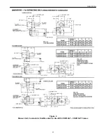
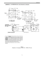
Page 34: ...GEH 5304A 34 Figure 3 Application Information for CD2512AT CD2813AT Frames ...

Page 35: ...GEH 5304A 35 Figure 4 Blower Unit Commutator End Mounted for Use With CD2512AT CD2813AT Frames ...

Page 36: ...GEH 5304A 36 Figure 5 Dimensions Air Openings for CD2512AT CD2813AT Frames ...

Page 37: ...ess Filter With Filter 8 5 Rabbet Less Tach Less Tach CD25XX 36A171113AAG01 36A171113AAG01 36A172476AAG01 36A171269AAG01 36A171270AAG01 CD28XX 36A171114AAG02 36A171114AAG01 36A167477AAG01 36A171269AAG01 36A171270AAG01 DC PY Tach Only DC BC 42 Tach Only DC BC 46 Tach Only Fits PY Kit Fits BC Kit Fits BC Kit 50V 1000 RPM 897A594 002 50V 1000 RPM 897A590 032 50V 1000 RPM 897A591 041 100V 1000 RPM 897...

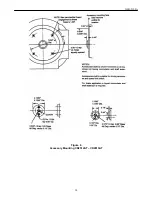
Page 38: ...GEH 5304A 38 Figure 6 Accessory Mounting CD2512AT CD2813AT ...

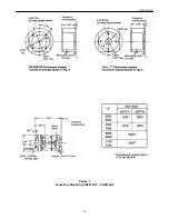
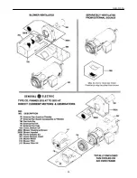
Page 39: ...GEH 5304A 39 Figure 7 Accessory Mounting CD2512AT CD2813AT ...

Page 40: ...GEH 5304A 40 ...

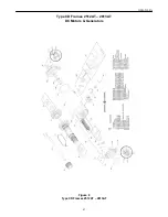
Page 41: ...GEH 5304A 41 Type CD Frames 2512AT 2813AT DC Motors Generators Figure 8 Type CD Frames 2512AT 2813AT ...

Page 42: ...ents Contents Organization Technical Accuracy Clarity Completeness Drawings Figures Tables Referencing Readability Specific Suggestions Corrections information that could be expanded on and such Page No Comments Other Comments What you like what could be added how to improve and such Overall Grade Compared to publications from other manufacturers of similar products how do you rate this publicatio...

Page 43: ...GEH 5304A 43 Detach and fax or mail to the address noted above ...

Page 44: ... 5304A 44 Fold here and close with staple or tape Place Stamp Here GE INDUSTRIAL SYSTEMS INDUSTRIAL ENGINEERING TECHNICAL PUBLICATIONS EDITOR 2000 TAYLOR STREET FORT WAYNE IN 46801 2205 USA Fold here first ...

Page 45: ...GEH 5304A 45 Document Revision History Rev Date Author ISAAC Description 0 12 14 99 GJG N A Conversion from PageMaker ...

Reviews: