46
06 Electrical Connection
User Manual
V1.0-2023-10-30
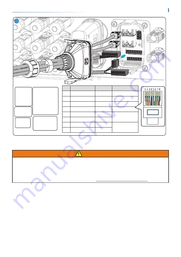
DRED/RCR:
11: COM/DRM0 or
REF_1
12: REFGEN or
REF_2
13: DRM 4/8 or DI_4
14: DRM 3/7 or DI_3
15: DRM 2/6 or DI_2
16: DRM 1/5 or DI_1
Dry Contact
1: DO1-
2. NC
3: DO1+
9: DO2-
10: DO2+
Power Supply
4: GND
5: 12V_S
RSD Control
5: 12V_S
6: RSD_12V
Remote Shutdown
7: GND
8: Remote Shutdown
PIN
Color
EMS/PAR
Definition
1
Orange and White
485A3
-
2
Orange
485B3
-
3
Green and White
NC
-
4
Blue
GND
signal ground wire
5
Blue and White
CAN_L
CAN bus
6
Green
CAN_H
7
Brown and White
SYN_BUS1
Parallel syn signal
8
Brown
SYN_BUS2
1
4
5
1
2
3
11 12 13 14 15 16
4 5 6 7 8 9 10
11 12 13 14 15 16
1
2
3
4 5 6 7 89 10
EMS/PAR
EMS/PAR
6�7�2 Connecting the BMS or Meter Communication Cable
WARNING
• For GEH15-3U-10 and GEH20-3U-10
, please connect the cable to BMS1 port to realize BMS
communication. Otherwise, BMS communication may fail.
• For GEH25-3U-10, GEH29.9-3U-10, and GEH30-3U-10
, please connect the cable to BMS1
port to realize BMS communication when single battery system is connected. Otherwise, BMS
communication may fail. For more details, refer to


