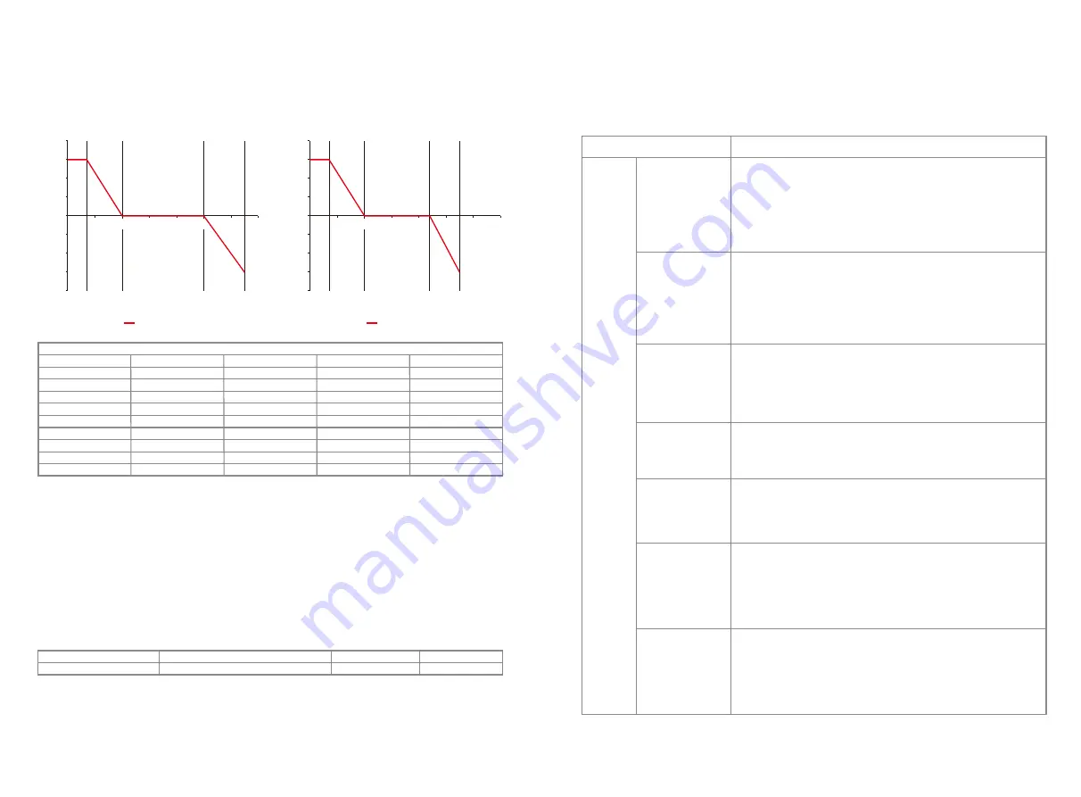
5.6.3 QU Curve Mode
QU curve mode can be modified by Modbus communication, specifically according to the
inverter Modbus address and Modbus register value, according to the set range to set the
corresponding value.
5.6.4 Power Recovery Rate
The power recovery rate can be modified by Modbus communication, specifically according to
the inverter Modbus address and Modbus register value, according to the set range to set the
corresponding value.
Function
Power recovery rate Settings
The default value (Australia & New Zealand)
16
(
16%Pn/min
)
Register
40536
Setting range
5~100
If you need to change the above Settings, please contact our after-sales service.
40%
V1
V2
V3
V4
LEADING
LEADING
VAR/RATED, VA (%)
INVERTER VOLTAGE, V
var characteristic curve
LEGEND:
30%
20%
10%
0%
10%
200
210
230
240
260
270
20%
30%
40%
220
250
40%
V1
V2
V3
V4
LEADING
LEADING
VAR/RATED, VA (%)
INVERTER VOLTAGE, V
var characteristic curve
LEGEND:
30%
20%
10%
0%
10%
200
210
230
240
260
270
20%
30%
40%
220
250
QU curve Mode
Function
QU curve mode enable or disable
V1 voltage ratio
Q1 reactive power ratio
V2 voltage ratio
Q2 reactive power ratio
V3 voltage ratio
Q3 reactive power ratio
V4 voltage ratio
Q4 reactive power ratio
Default value (Australia)
0
900 (207 V)
300 (30%*Pn)
957 (220 V)
300 (30%*Pn)
1087 (250 V)
300 (30%*Pn)
1152 (265 V)
300 (30%*Pn)
Default value (New Zealand)
0
900
(
207 V)
300
(
30%*Pn)
957 (220 V)
300 (30%*Pn)
1061 (244 V)
300 (30%*Pn)
1109 (255 V)
300 (30%*Pn)
Setting range
“0”or“1”
0~2000
0~600
0~2000
0~1500
0~2000
0~1500
0~2000
0~600
Register
40650
40653
40654
40655
40656
40657
40658
40659
40660
Example: Set the ratio of V1 voltage to 1100, corresponding to the rated voltage of 230 V, V1
=
230
* 110% = 253 V.
Example: Set Q1 reactive power ratio to 300, corresponding reactive power
Q1=30%*
rated
power.
6 Troubleshooting
If the Inverter is not able to work properly, please refer to the following instructions before
contacting your local service. If any problems arise, the red (FAULT) LED indicator on the front
panel will light up and the LCD screen will display relevant information. Please refer to the
following table for a list of error messages and associated solutions.
1. Disconnect DC switch, take off DC connector, check the impedance between
PV (+) & PV(-) to earth.
2. If impedance is less than 100 kΩ, please check the insulation of PV string wiring
to earth.
3. If impedance is large than 100 kΩ, please contact local service office.
4. Take off AC connector, measure the impedance between neutral wire and PE
line. If it is larger than 10KΩ, please check AC wiring.
1. Grid is not connected.
2. Check if the power cable is connected with grid.
3. Check the availability of power from the grid.
1. Check whether PV open circuit voltage is higher or too close to the maximum
input voltage.
2. If the problem still persist when PV voltage is less than the maximum input
voltage, contact local service office for help.
1. The internal temperature is higher than normal specified value.
2. Reduce ambient temperature.
3. Move the inverter to a cool place.
4. If the problem still exists, contact local service office for help.
1. The ground current is too high.
2. Take off the inputs from the PV panel and check the peripheral AC system.
3. When the problem is cleared, reconnect the PV panel and check the Inverter
status.
4. Contact local service office for help if the problem still persist.
1. The PV Inverter will automatically restart within 5 minutes if the grid returns to
normal.
2. Make sure grid voltage conforms to specifications.
3. Make sure neutral (N) wire and PE wire are well connected.
4. Contact local service office for help if the problem still persist.
1. Grid is not connected.
2. Check grid cable connection.
3. Check availability of grid.
Vac Failure
Fac Failure
Type of fault
Troubleshooting
Ground I Failure
Isolation Failure
Over Temperature
PV Over Voltage
Utility Loss
System
Failure
25
26


