19
20
Ethernet cable 120ohm termination resistor is controlled by dip switch. "ON" means connected, and
"OFF" means disconnected, illustrated as the above figure.
Selection mode of terminal resistance dial switch with 120ohm.
• When single inverter is in communication, dial the terminal resistance dial switch to ON state (The
default is OFF) which is next to the RS485 communication port of inverter, so that the RS485
terminal is with 120ohm.and make the shielding layer of munication line single-point grounding, as
shown in the last figure.
• If multiple inverters are in communication, connect all the inverters in a daisy chain through the
RS485 communication cable For device at the end of daisy chain, dial the terminal resistance dial
switch to ON state (The default is OFF), and make the shielding layerof communication line
single-point grounding.
4.4.2 WiFi Communication
This function is only applicable for WiFi model, for specific configurations, please refer to "WiFi/LAN
Configuration Instruction" in the attachment, and you can also refer to the description of "Demo
Videos Of Monitoring Installation" on the http://www.goodwe.com/DownLoad.aspx website.
After the configurations are completed, please register on the website www.gesolarinverter.com.
The WiFi module installation of series is shown in the below figure.
Cable requirements of RS485 communication: Shielded twisted-pair cable or shielded
twisted-pair.
The name and password of Wi-Fi cannot use symbols, only Arabic numerals or upper-
case /lowercase letters.
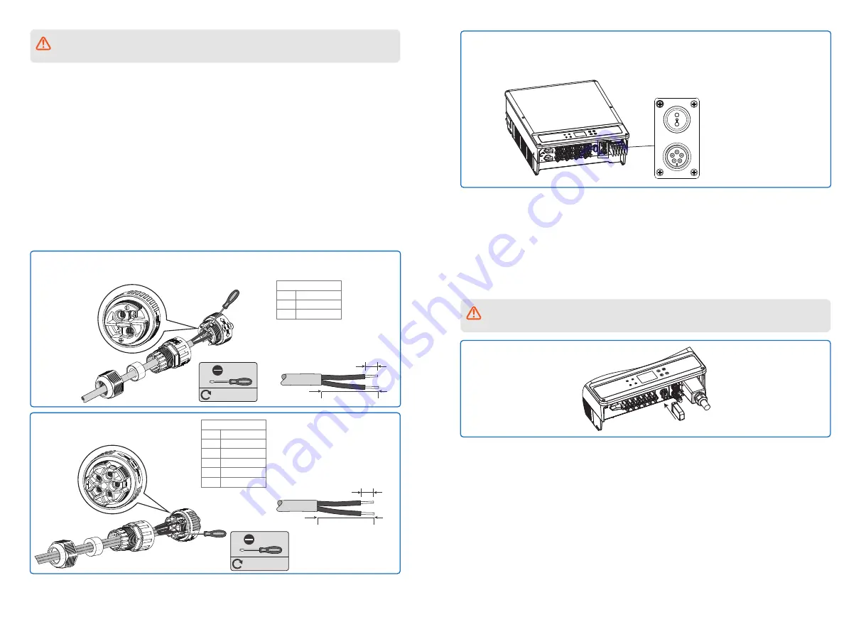
Remote shutdown(2pin) or RS485(5pin):
Step 1-1 For Remote shutdown(2pin):
Put the cable through the plate.
M3
0.6~0.8N·m
6.5mm
25mm
No.
+
-
Function
SC-A
SC-B
Remote shutdown
Step 2:
Connect the terminal to the right position onto the inverter.
Remote
shutdown
RS 485
Step 1-2 For RS485(5pin):
Put the cable through the plate.
M3
0.6~0.8N·m
5
3
4
5
1
2
6.5mm
25mm
No.
1
2
3
4
5
Function
RS485-A1
RS485-B1
RS485-A1
RS485-B1
NC
RS485


