03
04
3 Product Introduction
3.1 Intended Usage
The GEP series which is a Three or Six MPPT, three phase transformer-less grid-connected
inverter which is a crucial unit between the PV string and the utility grid in the PV power system.
Inverter is dedicated to converting directing current generated by the PV module into alternating
current, and feeding it into the utility grid, this conforms to parameters of the local utility grid. The
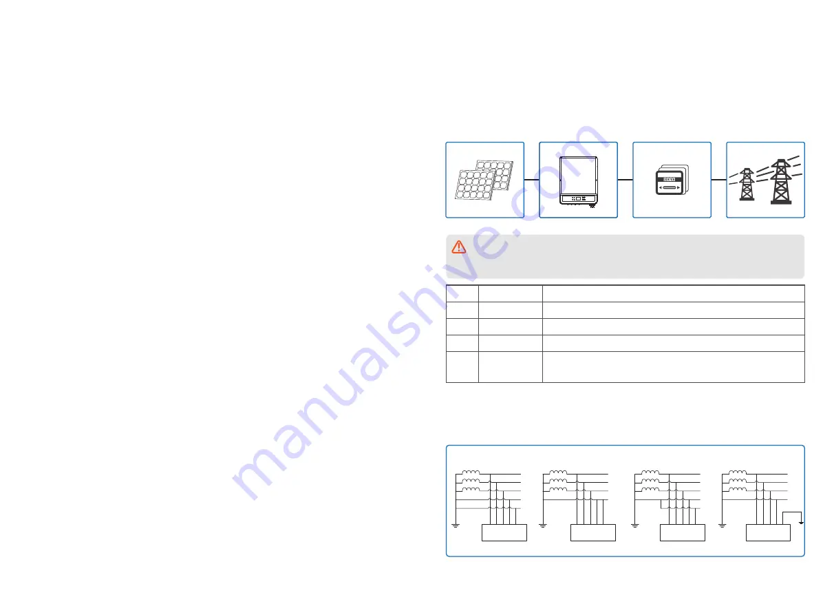
intended usage of inverter is illustrated in the below figure.
kW.H
A
B
C
D
GEP series
GEP12-L-10,GEP15-L-10,GEP20-L-10,GEP25-10,GEP30-10,GEP36-10,GEP29.9-10,GEP30-L-1
0,GEP35-L-10,GEP50-10,GEP60-10 support four different types(TN-S,TN-C,TN-C-S, TT) of grid.
please refer to the below figure.
The reason why the inverter can't be connected to the PV module is that the positive or
negative terminal should be grounded, except when a transformer has been used between
the inverter and grid.
Item
A
B
C
D
Description
PV string
Inverter
Meter device
Utility grid
Note
Monocrystalline silicon, polycrystalline silicon and others.
GEP Series
Meter cupboard with distributed generation system
TN-S, TN-C, TN-C-S, TT, IT
(different Model types with different types of utility grid as below)
TN-S
TN-C
TN-C-S
TT
L1
L2
L3
N
PE
PE
Transformer
Inverter
Transformer
L1
L2
L3
PEN
PE
Inverter
L1
L2
L3
N
PE
Transformer
PE
Inverter
L1
L2
L3
N
Transformer
PE
Inverter
2 Safety Measures & Warning
This manual contains important instructions for GEP series inverter that shall be followed during
installation of the inverter.
The GEP series for Three or Six MPPT, Three-Phase solar inverter without transformer, which
consists of GEP12-L-10, GEP15-L-10, GEP20-L-10, GEP25-10, GEP30-10, GEP36-10,
GEP29.9-10, GEP30-L-10,GEP35-L-10,GEP50-10 and GEP60-10 model type.
Model GEP50-10 and GEP60-10 are commercial and industrial PV inverters, cannot be used as
residential inverters.
The GEP Series have been designed and tested strictly according to the international safety
regulation. As electrical and electronic equipment, safety instructions related to them must be
complied with during installation, commissioning, operation. Incorrect or improper work may result
in damage to:
1. The life and well-being of the operator or a third party.
2. The inverter and other properties that belong to the operator or a third party. Therefore the
following safety instructions must be read and always kept in mind prior to any work. All detailed
work-related safety warnings and notes will be specified at the critical points in corresponding
chapter.
All installation and electrical work must only be performed by qualified personnel. They have:
•Been trained specially.
• Already completely read through and understood the manual and related documents.
• Be familiar with safety requirements for electrical systems.
The inverter must be installed and maintained by professionals in compliance with local electrical
standards regulations and the requirements of local power authorities or companies.
• Improper handling of this device will pose a risk of injury.
• Always follow the instructions contained in the manual when moving or positioning the inverter.
• The weight of the equipment can cause injuries, serious wounds or bruise if improperly handled.
• Please install it in a place beyond children's reach.
• Prior to installing and maintaining the inverter, it is crucial to make certain that the inverter in not
electrically connected.
• Before maintaining the inverter, disconnect the connection between the AC grid and the inverter
first, and then disconnect the connection between the DC input and the inverter, you should wait
at least 5mins after these disconnection in case of electric shock.
• All cables must be firmly attached, undamaged, properly insulated, and adequately dimen-
sioned.
• The temperature of some parts of the inverter may exceed 60
℃
during operation. To avoid
being burnt, do not touch the inverter during operation. Let it cool before touching it.
• Without permission, opening the front cover of the inverter is not allowed. Users should not
touch/replace any components of the inverter except the DC/AC connectors. Manufacturer will not
bear any consequences caused by unauthorized actions which will lead to potential injury to
people and damage to inverters.
• Static electricity may damage electronic components. Appropriate method must be adopted to
prevent such damage to the inverter; otherwise the inverter may be damaged and the warranty
will be annulled.
• Ensure that the output voltage of the proposed PV array is lower than the maximum rated input
voltage of the inverter; otherwise the inverter may be damaged and the warranty will be annulled.
• If the equipment is used in a manner not specified by the manufacturer, the protection provided
by the equipment may be impaired.
• When exposed to sunlight, the PV array will generate very high voltage which can cause
electrical shock hazard. Please strictly follow the instruction we provided.
• PV modules should have an IEC61730 class A rating.
• Prohibit inserting or pulling the AC or DC terminals when the inverter is operational. Or the
inverter will be destroyed.
Only DC connectors provided by Manufacturer are permitted for use, otherwise the inverter may
be damaged and the warranty will be annulled.
• The inverter can exclude the possibility of DC residual currents to 6mA in the system,Where an
external RCD is required in addition to the built-in RCMU, type A RCD must be used to avoid
tripping.
• The default photovoltaic module is not grounded.
• It is recommended to add a fuse when there is more than two PV string inputs into one MPPT.
The IP65 premise is that the machine is completely sealed. Please install it within one day after
unpacking, otherwise please block the unconnected port and do not open it to ensure that the
machine is not exposed to water and dust.


