13
14
4.3.2 AC Circuit Breaker And Residual Current Device
An independent three or four pole circuit breaker for each inverter must be installed at the output
side to ensure that the inverter can be securely disconnected from the grid.
The internal integrated residual current detection device (RCD) of inverter can detect external
leakage current in real time, when detecting the leakage current value exceeds the limit value, the
inverter will be disconnected from the grid as soon as possible. If an external RCD is installed , the
action current should be 500mA or higher.
4.3.3 Earth Terminal Connection
The inverter is equipped with earth terminal according to the requirement of EN 50178.
All non-current carrying exposed metal parts of the equipment and other enclosures in the PV
power system should be grounded.
Please connect 'PE' cable to ground.
1. Strip the wire insulation sheet of a suitable length with a wire stripper.
Output Current
31.5A
40A
54.5A
40A
43.3A
48A
53.3A
80A
96A
80A
96A
Inverter Model
GEP12-L-10
GEP15-L-10
GEP20-L-10
GEP25-10
GEP29.9-10
GEP30-10
GEP36-10
GEP30-L-10
GEP35-L-10
GEP50-10
GEP60-10
Recommended Nominal Current Of AC Breaker
>40A
>50A
>68A
>50A
>55A
>60A
>66A
>100A
>120A
>100A
>120A
L1
L2=L1 + (1~2mm)
2. Insert the stripped wire into the terminal and compress it tightly by crimping pliers.
It's not allowed for several inverter to use the same circuit breaker. It's not allowed to
connect loads between inverter and circuit breaker.
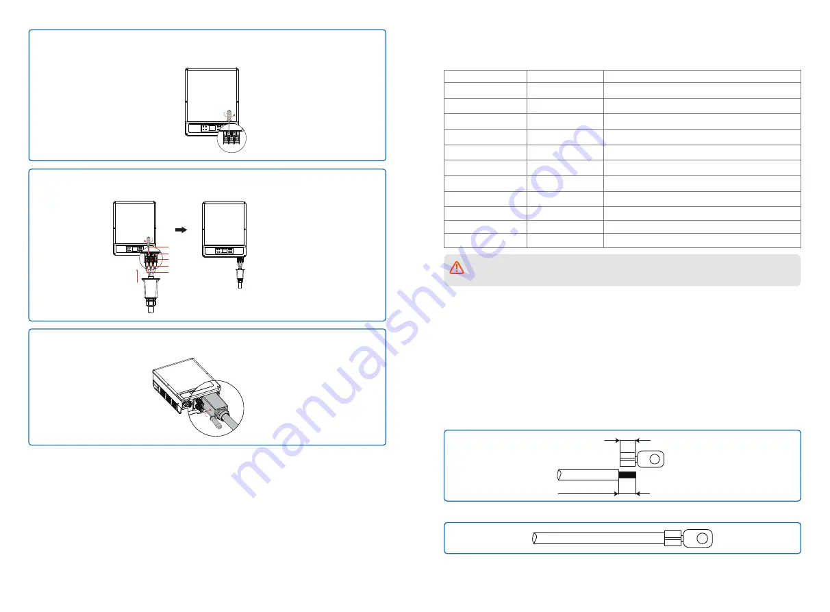
Step 4:
Unscrew the screws of the AC terminal clockwise using one flat-head screwdriver so
that all the five interfaces are ready to be connected with cables.
Step 6:
Install the AC cover and tighten the screws clockwise to fix the cover (Tightening torque:
1.0N.m0). Tighten the waterproof connector finally.
Step 5:
Connect the AC cables to the AC terminal in sequence and tighten the screws
clockwise.
N
PE
L3
L2
L1
Tightening torque
GEP12~20L-10: 3.0N.m
GEP25~36-10: 3.0N.m
GEP30~35L-10: 6.0N.m
GEP50~60-10: 6.0N.m


