background image

System Commissioning

30

User Manual V1.0-2022-05-05

No.

Icon

Description

J

-

System time and date.

K

E-Total icon

Historical cumulative power generation.

L

-

System status information.

M

Carbon icon

Energy conservation and emission reduction.

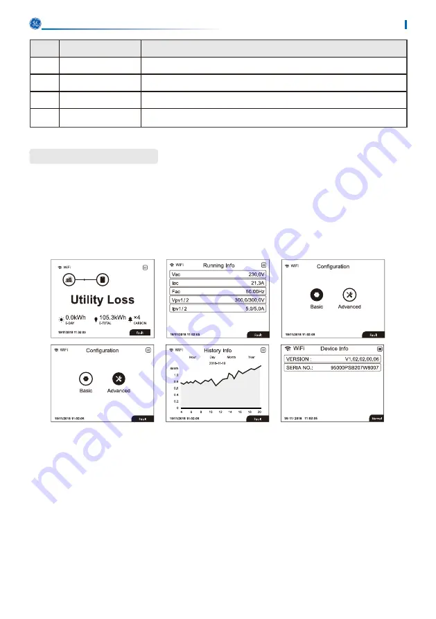
Main Menu

Level 1 menu interface through the up and down key cycle, in the historical information, 

configuration, advanced settings interface, press the Enter key will enter the Level 2 menu. To 

enter the Level 2 menu, select the item from the up and down keys. Press Enter to enter the 

project setup menu, go to the Level 3 menu, change the setting contents by pressing the up and 

down keys, and press the Enter key to set the contents. If safety country is not selected (shows 

'Configure Safety' on display at home page) , press any key to enter Safety Country page.

The main menus interfaces are presented below:

Summary of Contents for GEP3.5-1-10

Page 1: ...www gesolarinverter com V1 0 Grid Tied PV Inverter...

Page 2: ...guide cannot replace the product labels or the safety precautions in the user manual unless otherwise specified All descriptions here are for guidance only and other GE trademarks are trademarks of G...

Page 3: ...sonal Requirements 3 2 6 EU Declaration of Conformity 4 3 Product Introduction 5 3 1 Application Scenarios 5 3 2 Circuit Diagram 5 3 3 Supported Grid Types 5 3 4 Appearance 6 3 4 1 Appearance 6 3 4 3...

Page 4: ...lling the Communication Module optional 26 7 Equipment Commissioning 27 7 1 Check Before Power ON 27 7 2 Power On 27 8 System Commissioning 28 8 1 Indicators and Buttons 28 8 2 Setting Inverter Parame...

Page 5: ...al standards and electric systems This manual applies to the listed inverters below GEP or Inverter for short Model Nominal Output Power Nominal Output Voltage GEP3 5 1 10 3 5kW 220 230V GEP3 6 1 10 3...

Page 6: ...uctions For more warranty details please visit https www gesolarinverter com warranty html Notice The inverters are designed and tested strictly complies with related safety rules Read and follow all...

Page 7: ...terminals can be damaged All labels and warning marks should be visible after the installation Do not scrawl damage or cover any label on the device Inverters should not be installed in multiple phas...

Page 8: ...horization and Restriction of Chemicals EC No 1907 2006 REACH General Electric Company hereby declares that the inverter without wireless communication modules sold in the European market meets the re...

Page 9: ...to the utility grid The intended use of the inverter is as follows PV String Inverter Circuit Breaker Circuit Breaker optional Utility Grid 3 2 Circuit Diagram 3 3 Supported Grid Types For the grid ty...

Page 10: ...s 3 Communication Module Port Connect WiFi LAN WiFi LAN communication module 4 DRED Remote Shutdown Communication Cable Port Used to connect the DRED or remote shutdown communication cable 5 AC Output...

Page 11: ...S CONNECTED ACTIVE BLINK 2 WIRELESS ROUTER NOT CONNECTED BLINK 4 WIRELESS SERVER PROBLEM BLINK RS485 IS CONNECTED ON A FAULT HAS OCCURRED OFF NO FAULT 3 4 3 Indicators Power Operating SEMS Faulty No P...

Page 12: ...V1 0 2022 05 05 3 4 3 Nameplate The nameplate is for reference only GE trademark product type and product model Technical parameters Safety symbols and certification marks Contact information and seri...

Page 13: ...l complete contents and intact appearance Contact the supplier as soon as possible if any damage is found Notice The number of PV connectors and the PV terminals in the inverter is the same The type a...

Page 14: ...e or throw the desiccant away 2 Store the equipment in a clean place Make sure the temperature and humidity are appropriate and no condensation 3 The height and direction of the stacking inverters sho...

Page 15: ...avoid direct sunlight rain and snow Build a sunshade if it is needed 6 Do not install the equipment in a place that is easy to touch especially within children s reach High temperature exists when th...

Page 16: ...e down forward tilt back forward tilt or horizontally Mounting Support Requirements The mounting support shall be nonflammable and fireproof Make sure that the support surface is solid enough to bear...

Page 17: ...se other auxiliary tools on site if necessary Installation Tool Requirements Goggles Safety shoes Safety gloves Dust mask Diagonal pliers Marker Level Heat shrink tube Rubber hammer DC wiring wrench V...

Page 18: ...when moving the equipment NOTICE Avoid the water pipes and cables buried in the wall when drilling holes Wear goggles and a dust mask to prevent the dust from being inhaled or contacting eyes when dri...

Page 19: ...specifications shall meet local laws and regulations DANGER Disconnect the DC switch and the AC output switch of the inverter to power off the inverter before any electrical connections Do not work w...

Page 20: ...ng to the inverter Otherwise the inverter may be damaged permanently or even cause fire and cause personal and property losses 1 Make sure that the max short circuit current and the max input voltage...

Page 21: ...sed Otherwise the ingress protection rating will be influenced Step 1 Prepare DC cables Step 2 Crimp the crimp contacts Step 3 Disassemble the PV connectors Step 4 Make the DC cable and detect the DC...

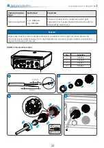
Page 22: ...Electrical Connection 18 User Manual V1 0 2022 05 05 MC4 PV connector 4mm2 S 6mm2 Click Click 600V Click Click 600V...

Page 23: ...25A GEP3 6 1 10 25A GEP4 2 1 10 32A GEP4 6 1 10 32A GEP5 0 1 10 32A Model RCD specifications GEP3 5 1 10 300mA GEP3 6 1 10 GEP4 2 1 10 GEP4 6 1 10 GEP5 0 1 10 A type A RCD Residual Current Device sha...

Page 24: ...connector Step 3 Insert the AC output cable into the AC connector Step 4 Plut the AC connector into the inverter Click NOTICE Make sure that the cable is connected correctly and securely Clear the deb...

Page 25: ...ntroduction Notice After completing cable connections set related parameters via LCD or SolarGo app to enable export power limit control or output power limit control Communication Type Definition Fun...

Page 26: ...far away from any interference source or power cable to prevent the signal from being influenced No Function 1 RS485 B 2 RS485 B 3 RS485 A 4 RS485 A RS485 Communication Cable Communication Type Defin...

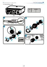
Page 27: ...Electrical Connection 23 User Manual V1 0 2022 05 05 CT Communication Cable No Function 5 CT 6 CT...

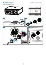
Page 28: ...Electrical Connection 24 User Manual V1 0 2022 05 05 DRED Communication Cable No Function 1 DRM1 5 2 DRM2 6 3 DRM3 7 4 DRM4 8 5 REFGEN 6 COM DRM0...

Page 29: ...Electrical Connection 25 User Manual V1 0 2022 05 05 Remote shutdown Communication Cable No Function 1 DRM4 8 2 REFGEN 1 DRM4 8 2 REFGEN...

Page 30: ...visit https www gesolarinverter com Plug a communication module into the inverter to establish a connection between the inverter and the smartphone or web pages The communication module can be a Bluet...

Page 31: ...re connected correctly and securely 3 Cable ties are intact routed properly and evenly 4 Unused ports and terminals are sealed 5 The voltage and frequency at the connection point meet the inverter gri...

Page 32: ...wn Enter and Esc buttons to toggle the main menus Press the Enter Esc key to toggle the 123 menu use the up and down keys to select the item and change the parameters and long press the Enter short pr...

Page 33: ...LAN and RS485 C LVRT HVRT icon The icon indicates that the system LVRT HVRT function is on D Grid Type icon The icon indicates the grid type selected including Delta Grid Star Grid E Power limit icon...

Page 34: ...cal information configuration advanced settings interface press the Enter key will enter the Level 2 menu To enter the Level 2 menu select the item from the up and down keys Press Enter to enter the p...

Page 35: ...r Manual V1 0 2022 05 05 Main Menu Basic Settings is mainly used to set the commonly used parameters including language settings time settings communication settings and safety setting And these param...

Page 36: ...e entered you can set the advanced settings menu for all items The default password is 1111 In order to prevent customers from forgetting the password all devices have a unique super password bound to...

Page 37: ...System Commissioning 33 User Manual V1 0 2022 05 05...

Page 38: ...System Commissioning 34 User Manual V1 0 2022 05 05...

Page 39: ...er generation and annual power generation information Step 1 Press Up Down to select Basic and press Enter Step 2 Press Up Down to select Communication and press Enter Step 3 Press Up Down to select W...

Page 40: ...settings Country Code Set the safety country region in compliance with the local grid standards and application scenario of the inverter Grid Connection Set to connect or disconnect the grid Error Lo...

Page 41: ...SolarGo APP User Manual Scan the QR code or visit https www gesolarinverter com images FILES DOWNLOADS 1 GLOBAL 4 USER MANUALS SolarGo 20 APP 20User 20Manual EN pdf to get the user manual SolarGo App...

Page 42: ...nting plate Step 3 Remove the mounting plate Step 4 Store the inverter properly If the inverter needs to be used later ensure that the storage conditions meet the requirements 9 3 Disposing of the Inv...

Page 43: ...ystem 3 When the problem is cleared reconnect the PV panel and check the Inverter status 4 Contact local service office for help if the problem still persist Vac Failure 1 The PV Inverter will automat...

Page 44: ...ge is lower than 250V please check configuration of inverter module 4 If PV array voltage is higher than 250V please contact local service office Others Wi Fi module fail to connect to network 1 If th...

Page 45: ...ths DC Switch Turn the DC switch on and off ten consecutive times to make sure that it is working properly Once a year Electrical Connection Check whether the cables are securely connected Check wheth...

Page 46: ...umber of Strings per MPPT 1 1 1 Output Nominal Output Power W 3500 3600 4200 Nominal Output Apparent Power VA 3500 3600 4200 Max AC Active Power W 3500 3960 4620 Max AC Apparent Power VA 3500 3960 462...

Page 47: ...h Integrated DC Surge Protection Type II AC Surge Protection Type II General Data Operating Temperature Range 25 60 Relative Humidity 0 100 Max Operating Altitude m 4000 Cooling Method Natural Convect...

Page 48: ...Output Nominal Output Power W 4600 5000 Nominal Output Apparent Power VA 4600 5000 Max AC Active Power W 4600 5500 Max AC Apparent Power VA 4600 5500 Nominal Power at 40 W Only for Brazil 4600 5000 Ma...

Page 49: ...II AC Surge Protection Type II General Data Operating Temperature Range 25 60 Relative Humidity 0 100 Max Operating Altitude m 4000 Cooling Method Natural Convection Display LED LCD Communication WiFi...

Page 50: ...mark of General Electric Company and is used under license by GoodWe Technologies Co Ltd 2022 All Rights Reserved www gesolarinverter com sales gesolarinverter com support gesolarinveter com Local Con...

Reviews: