IMPORTANT SAFETY INSTRUCTIONS.
READ ALL INSTRUCTIONS BEFORE USING.
The power cord and/or connections must comply
with the National Electrical Code, Section 422
and/or local codes and ordinances.
For Models Not Equipped with a Cord:
1. Chose a power cord not less than H05VV-F,
3G1.0mm2 incorporate with a plug rated 250V
13A (fuse in plug: 250V, 10A) approved by BSI
which matched ground wire for UK market
(Standard: BS1363-1) or a plug rated 250V 16A
approved by VDE with matched ground wire
(Standard: DIN VDE 0620-1)
2. Chose a power cord not less than H05VV-F,
3G1.0mm2 and fi tted with a switch, the switch
shall be directly connected to the supply
terminals and shall have a contact separation
in all poles, providing full disconnect under
overvoltage category III conditions(the full
disconnection not less than 3mm).
3. Make sure the switch shall be easily visible and
accessible. The recommend distance between
this appliance and electrical switch is within
2m.
To Attach a Power Cord:
GROUNDING INSTRUCTIONS:
This appliance
must be grounded. In the event of malfunction
or breakdown, grounding provides a path of least
resistance for electric current to reduce the risk of
electric shock. The power cord (to be installed)
must have an equipment-grounding conductor and
a grounding plug. The plug must be plugged into
an appropriate outlet that is properly installed and
grounded in accordance with all local codes and
ordinances.
DANGER:
Improper connection of the
equipment-grounding conductor can result in
a risk of electric shock. Check with a qualifi ed
electrician or serviceman if you are in doubt as to
whether the appliance is properly grounded.
NOTE:
Disconnect electric power to disposer circuit before
installation. Turn the circuit breaker to the
OFF
position or remove the fuse.
A. Connect the disposer to 220-240 Volt,
50-60 Hz AC current only.
B. If a plug-in cord is used, use a three-prong plug.
Ground wire should be attached to the ground
screw in the bottom of the disposer (end bell).
WARNING!
▲
!
HOW TO CONNECT ELECTRICITY (cont.)
SAVE THESE INSTRUCTIONS
READ AND FOLLOW THIS SAFETY INFORMATION CAREFULLY
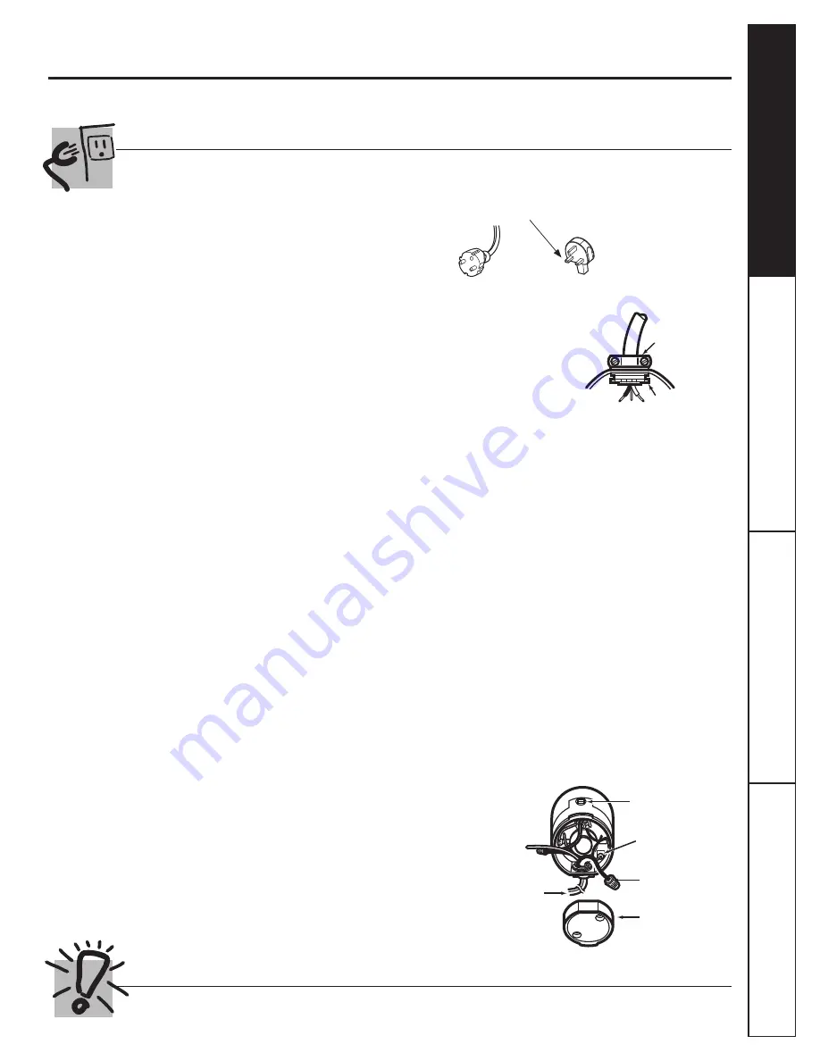
C. Use a cable clamp strain
relief connector where
power cord enters the
disposer.
To Wire Your Disposer Directly into the House
Current:
GROUNDING INSTRUCTIONS:
This appliance
must be connected to a grounded, metal,
permanent wiring system; or an equipment-
grounding conductor must be run with the circuit
conductors and connected to the equipment-
grounding terminal or lead on the appliance.
A. If you use BX cable:
1.
These products are designed for household use.
2.
Connect line wire to blue lead of disposer with a
wire nut. Connect neutral wire to brown lead of
disposer with a wire nut. Connect bare ground
wire to the ground screw. The ground wire
should be clamped and held by a strain relief.
3.
Do not use a rigid conduit for the wiring
connection.
4.
A dedicated acceptable motor switch, with the
off position marked, shall be provided for this
disposer at the time of installation. The switch
shall be mounted in sight of the disposer or the
sink opening for the disposer.
If BX cable is not used, provide a separate ground
wire to nearest reliable ground, using the screw in
the end bell for the ground wire.
www.GEAppliances.com
Strain Relief
Nut
If you are not familiar with electrical power and procedures, call a qualifi ed electrician.
3
Installation Instr
uctions
Oper
ating Instr
uctions
Tr
oubleshooting tips
Saf
ety Instr
uctions
NOTE:
When viewing
face of electrical plug
with grounding pin
at top, the left blade
is connected to the
identifi ed wire.
Trace the lead connected to this
blade marked “L” and attach that
lead to blue wire on disposer.
Red Reset Button
Ground Screw
Wire Nuts
Remove
Bottom Cap
To House Current
or Power Cord
Bottom of the
Disposer (end bell)
Summary of Contents for GFC1001V Series
Page 1: ...2 Ö Ç ø REV 1 1 1 GFC501 701 1001 GE 1 PANTONE BLACK C 2 3 A4 70 7710000000 0 4 1 ...
Page 5: ... Part Number PM3X215 ...
Page 6: ......
Page 8: ......
Page 10: ...Installation Instructions Operating Instructions Troubleshooting tips Safety Instructions 9 ...
Page 11: ...Installation Instructions Operating Instructions Troubleshooting tips Safety Instructions ...
Page 12: ...Installation Instructions Operating Instructions Troubleshooting tips Safety Instructions ...
Page 16: ... Parte No PM3X215 ...
Page 17: ......
Page 19: ......
Page 21: ...Instalación Operación Solucionar problemas Seguridad 9 ...
Page 22: ...Instalación Operación Solucionar problemas Seguridad ...
Page 23: ...Instalación Operación Solucionar problemas Seguridad ...


