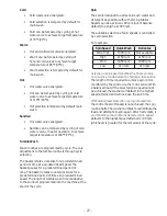
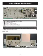
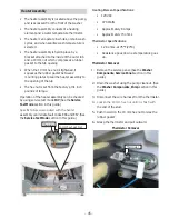
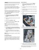
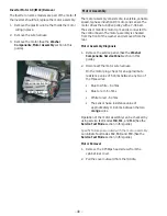
background image

– 33 –

  Control Board

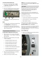
The control board is mounted in a housing that is attached to the inside of the control panel. The control 

board and housing are replaced as an assembly. The control board assembly is held in place by Phillips head 

VFUHZV7KHFRQWUROERDUGLVSURJUDPPHGWRUHFRJQL]HGLȺHUHQWPRGHVRIRSHUDWLRQ

Operation of the control board can be checked by using the Service Test Mode. (See the Service Test Mode 
section in this guide.)

6SHFL¿FIDLOXUHVDVVRFLDWHGZLWKWKHFRQWUROERDUGFDQLQLWLDWHIDXOWFRGHV((DQG(6HH

the Service 

Test Mode section in this guide.)

Mode Name

Description

Idle

No cycle is selected. All LEDs, 7-segment display on front panel, load selections and 

RSWLRQVDUHRȺ7KHGRRULVXQORFNHG7KHFRQWUROERDUGLVUHDG\WRWDNHLQSXWIURPWKH

user.

Standby

A cycle is selected with the appropriate load selections and options. LEDs and 

7-segment display on front panel are on. The door is unlocked. The control board is 

ready to take user input to either modify cycle selections or start a selected cycle.

Run

The control board is executing the currently selected cycle. The door is locked.

Pause

The control is stopped by the user during the execution of a cycle. The LEDs and 

VHJPHQWGLVSOD\RQWKHIURQWSDQHOVWD\RQDOOORDGVDUHWXUQHGRȺ7KHGRRULV

unlocked. The control board is ready to take user input to either modify, resume, or 
cancel the cycle.

End of Cycle

A cycle is completed. The LEDs and 7-segment display on the front panel stay on, all 

ORDGVDUHWXUQHGRȺ7KHGRRULVXQORFNHG7KHFRQWUROERDUGUHPDLQVLQWKLVPRGH

until the door is opened or after 2 hours have passed.

Fault

The control board detected a critical failure condition. The 7-segment display shows 

WKHIDXOWFRGHDOOORDGVDUHWXUQHGRȺ7KHIDXOWFRGHFDQRQO\EHUHPRYHGLQWKH

service test mode. (See the Service Test Mode section in this guide.)

Summary of Contents for GFW400SCK

Page 1: ...ces Louisville Kentucky 40225 31 9261 GE Appliances Front Load Washer Technical Service Guide December 2016 GE Appliances GFWS1705H GFWS1700H GFWN1600J GFWN1300J GFWH1200H GFWN1100H GFW400SCK GFW450SPK GFW450SSK ...

Page 2: ...ith its use WARNING To avoid personal injury disconnect power before servicing this product If electrical power is required for diagnosis or test purposes disconnect the power immediately after performing the necessary checks RECONNECT ALL GROUNDING DEVICES If grounding wires screws straps clips nuts or washers used to complete a path to ground are removed for service they must be returned to thei...

Page 3: ...peration Overview 26 Basic Wash Cycle 26 Component Locator Views 28 Control and Inverter Board Connections 30 Washer Components 31 Top Panel 31 Service Panel 31 Control Panel 32 Control Board 33 Programming the Control Board 34 Door Lock 34 Door Strike 35 Front Panel 36 Line Filter 36 Dispenser Assembly With Motor Driven Cam 37 Dispenser Assembly Without Motor Driven Cam 37 Dispenser Motor 40 Wate...

Page 4: ...sembly 45 Inverter 47 Motor Assembly 48 Door 50 Door Hinge 52 Tub Gasket Boot 52 Dampers 54 Wash Basket 55 Outer Tub Assembly and Suspension 57 Service Test Mode 59 Fault Codes 62 Schematics 67 Warranty 69 Index 70 ...

Page 5: ...Safety Requirements Steel Toed Work Boot Electrically Rated Glove and Dyneema Cut Resistant Glove Keeper Dyneema Cut Resistant Glove Plano Type Safety Glasses Prescription Safety Glasses Safety Glasses must be ANSI Z87 1 2003 compliant Brazing Glasses Cut Resistant Sleeve s Step 1 Plan and Prepare Step 4 Apply LOTO device and lock Step 2 Shut down the appliance Step 5 Control discharge stored ener...

Page 6: ...21 S 2020 R 2019 M 2018 L 2017 H 2016 G 2015 F 2014 D 2013 A The nomenclature tag is located on the bottom front corner on the right side of the cabinet NOTE The technical sheet is located behind the control panel Brand G GE Appliances H Hot Point G F W S 1 7 0 5 H 0 D G Engineering Revision Alpha or Numeric Model Year G Configuration F Front Load T Top Load Rear Control N Top Load Front Control U...

Page 7: ...HO 6HUYLFH WHVW PRGH EXLOW LQ 6SHFL F ZDVKHU FRPSRQHQWV FDQ EH RSHUDWHG Error codes are recorded and accessible on the control panel s 7 segment display Two piece plastic outer tub is formed from tough lightweight polypropylene The wash tub is constructed of durable stainless steel Two suspension springs and four GDPSHUV SURYLGH PD LPXP RȺ EDODQFH ORDG SURWHFWLRQ ZLWK PLQLPDO YLEUDWLRQ WUDQVIHU WR...

Page 8: ... 8 Control Features Model GFWN1600 Washer with Time Saver Model GFWH1200 Models GFW400 GFWN1100 and GFWN1300 Models GFW450 GFWS1700 and GFWS1705 Steam Washer with Time Saver ...

Page 9: ...ing the Sanitize cycle Sanitize with Oxi on some models The Sanitize with Oxi cycle when using an Oxi additive along with a detergent is designed to remove 99 9 of bacteria found in home laundry Measure the detergent and the Oxi products carefully Using the amounts appropriate for a large heavily soiled load follow the detergent and the Oxi product label instructions The detergent should be added ...

Page 10: ...ets Active Wear or Power Clean depending on model Bulky Bedding or Sanitize cycles To use 1 Turn power ON and select a wash cycle 2 Select the Add Steam button to activate steam 3 Press the Start Pause button 4 Soil Change the Soil level to increase or decrease the wash time to remove GLȺHUHQW DPRXQWV RI VRLO To change the Soil level press the Soil level button until the desired setting as been re...

Page 11: ...efore washing a load To change the saved cycle set the desired settings and hold down the My Cycle button for 3 seconds NOTE When using My Cycle wash RSWLRQV FDQQRW EH PRGL HG DIWHU WKH cycle has been started NOTE If wash options are changed with the My Cycle before starting the cycle the My Cycle OLJKW ZLOO WXUQ RȺ and the user will be returned to the base cycle 8 PreWash on some models Prewash i...

Page 12: ...epending on model Delay Wash Delay the start of a wash cycle for up to 24 hours Press the Delay Wash button to choose the amount of time wanted to delay the start of the wash cycle Once the desired time is reached press the Start button The machine will count down and start automatically at the correct time NOTE If it is forgetten to fully close the door a reminder signal will beep as a reminder t...

Page 13: ...a brief tumble and then proceeds to soak the clothes with water and GHWHUJHQW IRU D VSHFL HG SHULRG RI time Once complete the cycle will begin automatically PreSoak must be selected prior to pressing Start The PreSoak time will add an additional 30 minutes to the overall wash time LJK HȻFLHQF GHWHUJHQW IURP WKH main wash compartment in the dispenser is used for the PreSoak period and main wash cyc...

Page 14: ...f the washer is running pressing it once will pause the washer and unlock the door It will take a few seconds for the door to unlock after pressing Pause Press again to restart the wash cycle NOTE If the washer is paused and the cycle is not restarted within 15 minutes the current wash cycle will be cancelled NOTE In some cycles the washer will GUDLQ UVW WKHQ XQORFN WKH GRRU ZKHQ it is paused NOTE...

Page 15: ...Liquid detergent will drain into the washer drum as it is added Detergent usage may need to be adjusted for water temperature water hardness size and soil level of the load Avoid using too much detergent in the washer as it can lead to over suds ing and detergent residue being left on the clothes The Detergent Compartment LJK HȻFLHQF GHWHUJHQW LV required for this washer Use the detergent manufact...

Page 16: ...n the center when the insert is in position NOTE Not all models have the 2x and 3x detergent settings Some have only UHJXODU KLJK HȻFLHQF GHWHUJHQW settings Reduce the amount of detergent for 2x or 3x detergent per bottle instructions Move the insert by pulling it up and replace it by sliding it down between either the rear or front detergent compartment molded rails as desired for liquid detergen...

Page 17: ...If desired measure out the recommended amount of liquid bleach not to exceed 1 3 cup 80 ml and pour into the right compartment labeled LIQUID BLEACH R QRW H FHHG WKH PD LPXP OO OLQH 2YHU OOLQJ FDQ FDXVH HDUO GLVSHQVLQJ of the bleach which could result in damaged clothes NOTE Do not use powdered bleach in the dispenser The Fabric Softener Compartment IMPORTANT The fabric softener compartment positi...

Page 18: ... up the pour spout 8 Close the access door by hooking WKH ERWWRP WDEV UVW WKHQ rotating the access door shut Dispenser Drawer Area Detergent and fabric softener may build up in the dispenser drawer Residue should be removed once or twice a month 5HPRYH WKH GUDZHU E UVW pulling it out until it stops Then reach back into the left or right rear corner depending on model of the drawer cavity and press...

Page 19: ...locking the holes behind the gasket While holding down the door gasket inspect the interior gasket by pulling LW GRZQ ZLWK QJHUV 5HPRYH DQ foreign objects if found trapped inside this gasket Make sure there is nothing blocking the holes behind the gasket KHQ QLVKHG FOHDQLQJ WKH GRRU gasket remove hands and the gasket will return to the operating position Using the Washer ...

Page 20: ...rench 8 mm Socket Wrench WARNING Due to the size and weight of the washer or dryer and to reduce the risk of personal injury or damage two people are required for proper installation NOTE DO NOT remove washer shipping bolts prior to pedestal installation Shipping bolts MUST be reinstalled if previously removed Care should always be taken when laying the washer or dryer on its side to prevent compo...

Page 21: ...both protrusions on each pad are inserted in the holes on the top of the pedestal 7 Place the pedestal against the bottom of the washer or dryer Ensure that the drawer front is at the front of the washer or dryer 8 Align the holes in the pedestal with the holes in the bottom of the washer or dryer base 9 Use a Phillips head screwdriver to install the 4 8 mm bolts through the pedestal and into the ...

Page 22: ... side to side and front to back 15 Use an open end or adjustable wrench to adjust the legs in or out Tighten the locknuts against the bottom of the pedestal NOTE To minimize vibration the locknuts must be tight 16 Ensure that the slides are closed then slide the drawer into the opening 17 Align the drawer supports to the slides on each side 18 Reinstall the original screws in each drawer slide NOT...

Page 23: ...anufactured home Location Requirements When installed in a location other than an alcove or closet the minimal clearances to combustible surfaces and for air opening are 0 inches on both sides and 1 inch at the rear NOTE If the dryer is approved for installation in an alcove or a closet it will be stated on a label on the back When installed in an alcove or closet Minimum clearance between dryer c...

Page 24: ...brackets 3 5HPRYH WKH DGKHVLYH EDFNLQJ DQG UPO SODFH the 4 rubber pads over the leg brackets 4 Align the holes in the left bracket with the holes in the bottom left corner of the dryer Attach the bracket using 2 12 x 1 in Phillips head screws 5 Align the holes in the right bracket with the holes in the bottom right corner of the dryer Attach the bracket using 2 12 x 1 in Phillips head screws Conti...

Page 25: ... washer control panel and place the dryer on top of the washer 9 Align the holes in the brackets with the holes in the back of the washer Attach the brackets to the washer using 4 8 x 1 2 in Phillips head screws Do not push on the dryer after it is stacked on the washer Pushing on the dryer may result in pinched QJHUV Caution Use felt pads or other sliding device to DVVLVW PRYLQJ DQG WR SURWHFW ÀR...

Page 26: ...anged EXTRA RINSE PRE WASH SOIL LEVEL SPIN SPEED WASH TEMP Select EXTRA RINSE and PRE WASH options Use the SIGNAL button to change the volume level of the end of cycle signal Select the SOIL LEVEL to increase or decrease wash WLPH QHHGHG WR UHPRYH GLȺHUHQW DPRXQWV RI VRLO 6HOHFW WKH 63 1 63 WR FKDQJH WKH QDO VSLQ VSHHG of the cycles Follow the fabric manufacturer s care label when selecting spin s...

Page 27: ... at a predetermined speed The length of tumble wash time is adaptive to the soil level programmed into the machine at the start of the cycle Spin The spin is designed to extract as much water and detergent as possible without harming fabrics Speeds can be as slow as 90 rpm out of balance default to as high as 1000 rpm The available selection of spin speeds is controlled by cycle selection For exam...

Page 28: ...let Hose 3 Way Pipe Dispenser Assembly Water Valve Outlet Hose 3 Way Pipe Dispenser Inlet Hose Dispenser Assembly Water Valve Line Filter Water Level Sensor Nozzle Hose Thermistor Heating Element Pump Outlet Hose Tub Drain Hose Pump Damper Inverter Motor Thermistor Heating Element Inverter Motor Tub Drain Hose Damper Pump Outlet Hose Pump ...

Page 29: ... 29 Component Locator Views Continued Tub Drive Pulley Belt Motor Tub Drive Pulley Belt Motor Dispenser Drawer Dispenser Drawer ...

Page 30: ...alves CN5 Door lock output and line output to heater CN7 Inverter communication CN8 Line output to inverter and pump and cold water valve 2 and neutral output to heater CN13 Dispenser switch and thermistor Inverter Board CN13 CN7 CN8 CN3 CN1 CN5 CN4 CN2 CN7 CN13 CN2 CN8 CN3 CN5 CN4 CN1 Communication To Control Board Output To Motor 120VAC Iutput 120 VAC Input Output to Motor Communication to Contr...

Page 31: ... LV KHOG LQ SODFH by a top cover and 3 screws on the back Top Panel Removal 1 Remove the 3 Phillips head screws that attach the top cover then pull the cover rearward NOTE It may be helpful to place a putty knife along the top seam between the cover and control panel then tap lightly rearward 2 Slide the top panel rearward 1 inch then lift the panel Rear View Removal of the service panel provides ...

Page 32: ...ssembly Removal For 1100 1200 and 1300 1 Remove the top panel See Top Panel section 2 Pull the dispenser out to the stop position Press down on the lock tab Pull the dispenser out 3 Remove the 2 Phillips head screws from the control panel dispenser recess 4 Remove the 3 Phillips head screws that attach the top of the control panel to the control panel cover 5 Lift the top edge of the panel to dise...

Page 33: ...load selections and options LEDs and 7 segment display on front panel are on The door is unlocked The control board is ready to take user input to either modify cycle selections or start a selected cycle Run The control board is executing the currently selected cycle The door is locked Pause The control is stopped by the user during the execution of a cycle The LEDs and VHJPHQW GLVSOD RQ WKH IURQW...

Page 34: ...st select 3 3 Press and hold the Start key for 3 seconds or until a second beep is sounded 4 Press the Power key to reset the control Programming the Control Board The door lock contains a door switch and solenoid operated locking and unlocking mechanism A release hook located at the middle allows for manual unlocking of the door The door locks when a cycle is entered Wake up routine and during ev...

Page 35: ...RNING To avoid injury ensure all mechanical movement has stopped 2 Remove the service panel See the Washer Components Service Panel section in this guide 3 Reach behind and up the right side of the front panel push the release hook down then open the door Door Strike Removal 1 Open the door 2 Remove the 2 Phillips head screws that hold the door strike to the door frame cover 3 Remove the door stri...

Page 36: ...ts Door Lock section in this guide 5 Position the gasket behind the front panel door opening Close the door 6 Remove the 4 Phillips head screws that attach the front panel to the cabinet 7 Lift up then remove the front panel from the 2 hooks 7KH OLQH OWHU KHOSV WR VPRRWK RXW DQ ÀXFWXDWLRQV LQ voltage protecting the control board and providing PRUH UHOLDEOH RSHUDWLRQ 7KH OLQH OWHU LV LQVWDOOHG RQ t...

Page 37: ...es into SRVLWLRQ EHIRUH OO WDNHV SODFH Operation of the dispenser can be checked by using service test mode t12 See Service Test Mode 6SHFL F IDLOXUHV DVVRFLDWHG ZLWK WKH GLVSHQVHU FDQ initiate fault codes E38 and E39 See the Service Test Mode section in this guide Position Dispenser Function 1 Pre Wash 2 Wash 3 Fabric Softener 4 Bleach Caution When testing the dispenser motor DO NOT remove the wi...

Page 38: ...rgent Softener Bleach RW YDOYH RSHQ ZDWHU OOV IURP HWHUJHQW ER ROG YDOYH RSHQ ZDWHU OOV IURP OHDFK ER Hot Valve Cold Valve 2 Cold Valve 1 Detergent Softener Bleach Hot Valve Cold Valve 2 Cold Valve 1 Detergent Softener Bleach ROG YDOYH RSHQ ZDWHU OOV IURP HWHUJHQW box Cold valve 1 and Cold valve 2 open together ZDWHU OOV IURP 6RIWHQHU ER ...

Page 39: ...essure to the dispenser and nozzle When removing the inlet hose the inlet tube may remain in the hose Ensure the inlet tube is fully inserted into the tank inlet upon reassembly Caution A small retainer for the dispenser motor wiring located underneath the unused inlet is fragile To avoid breakage use minimal outward pressure when releasing wiring 3 Release the dispenser motor wiring from the reta...

Page 40: ...FL F IDLOXUHV DVVRFLDWHG ZLWK WKH dispenser motor can initiate fault codes E38 and E39 See the Service Test Mode section in this guide Dispenser Motor Removal Access the dispenser assembly See the Washer Components Dispenser Assembly sections in this guide Caution Lock tabs on the dispenser motor wiring harnesses are fragile Tab breakage can occur if excessive release pressure is applied 1 Disconn...

Page 41: ...er Level Control Operation When the machine is empty there is no water in the outer tub and no pressure in the air chamber the sensor will output the empty frequency signal As the water level rises the air pressure in the air chamber increases the water sensor frequency will change as the pressure change until the foam level reach the tumble begins Water temperature LV UHDG E WKH WKHUPLVWRU DQG OO...

Page 42: ...e hose loose by inserting a small f at blade screwdriver under the hose to break the seal c Remove the hose Pull the bottom of the water level control outward rotate it a quarter turn clockwise to clear the suspension spring 2YHUÀRZ DWHU HYHO The water valve assembly consists of 2 valve body DQG VROHQRLG FRLOV 7KH ZDWHU YDOYH KDV D ÀRZ UDWH of 2 1 gallons 8 liters per minute It is inserted and ret...

Page 43: ...vent foreign objects from entering the pump impeller and drain outlet The pump runs whenever the washer is in the spin function of a cycle The pump runs if the water level control RYHUÀRZ VZLWFK LV FORVHG DQG WKH ZDVKHU LV SOXJJHG LQ 2YHUÀRZ SURWHFWLRQ The pump is capable of eliminating 17 gallons 64 liters per minute Recommended minimum standpipe diameter is 1 1 4 inches Standpipe maximum height ...

Page 44: ...emove the drain hoses from the pump NOTE 7KH GUDLQ KRVHV DUH GLȻFXOW WR UHPRYH a Squeeze each clamp and slide it back b Carefully break each hose loose by inserting D VPDOO ÀDW EODGH VFUHZGULYHU XQGHU WKH hose to break the seal c Remove the tub outlet hose from the pump inlet d Remove the drain hose from the pump outlet 5 Disconnect the 2 wires from the pump 6 Remove the 2 Phillips head screws tha...

Page 45: ... using service test mode t07 See the Service Test Mode section in this guide 6SHFL F IDLOXUHV DVVRFLDWHG ZLWK WKH KHDWHU assembly can initiate fault codes E66 and E67 See the Service Test Mode section in this guide HDWLQJ OHPHQW 6SHFL FDWLRQV 120 VAC 970 Watts Approximately 8 Amps Approximately 15 ohms 7KHUPLVWRU 6SHFL FDWLRQV 12 K ohms at 75 F 24 C Resistance goes down as temperature goes up Ther...

Page 46: ...n this guide 3 Disconnect the blue and the purple wires from the heater and the wire harness from the thermistor 4 RRVHQ WKH PP KH QXW XQWLO LW LV ÀXVK ZLWK the end of the stud 5 Push inward on the 10 mm hex nut to relax the rubber gasket 6 Grasp the heater assembly and pull outward Heater Assembly Reinstallation 1 Slide the heater assembly into the tub opening and inside the bracket attached to t...

Page 47: ...at holds the motor wiring in place 6 Remove the single Phillips head screw that holds the front leg of the inverter to the base pan 7 Slide the inverter rearward to clear the guides that hold the rear of the inverter to the chassis Remove the inverter through the enlarged opening on the left side of the front frame Wire Tie W W W W W W W W W W Wi W W W W W W W W W W W W W W W W W W W W W W W W Wi ...

Page 48: ...r Motor Assembly Diagnosis 1 Remove the service panel See the Washer Components Service Panel section in this guide 2 Disconnect the motor wire harness On the motor plug check for an approximate resistance value of 6 ohms between any two of the three wires Blue to white 6 ohms Blue to red 6 ohms White to red 6 ohms The sensor has a resistance value of approximately 118 ohms between the two orange ...

Page 49: ...tite Part WX5X1005 to the bolt threads Ensure that the motor arm is at the lowest position under the motor bolt before tightening 5 Rock the motor rearward to clear the motor mounts from the outer tub Place the motor on the washer chassis 6 Disconnect the motor wire harness 7 Press the lock tab and remove the motor ground wire 8 Remove the plastic wire tie that holds the motor wire harness and gro...

Page 50: ...hese units Door Door Component Removal 1 Remove the 3 Phillips head screws that hold the hinge cover to the door Lift the hinge cover from the door 2 Remove the 4 Phillips head screws that hold the door to the hinge door plate 120VAV Input Communication port Communication Port 120 VAC Input ...

Page 51: ...llips head screws that hold the door cover and door strike to the door frame 4 Grasp and unsnap the door cover from the door frame 5 Lift the door glass out of the door frame NOTE The door handle door frame and protect cover are replaced as an assembly Door Glass Door Glass Door Handle Door Frame protect cover Door Frame Door Handle Protect Cover ...

Page 52: ... the short screw on the top Damage to the dispenser inlet may result if the wrong screw length is used 6 Push the tub assembly back while pressing the hinge arm inward and carefully remove the door hinge through the opening The tub gasket provides a watertight seal between the front and the outer tub The front of the tub JDVNHW LV VHFXUHG WR WKH IURQW SDQHO ÀDQJH E D spring and wire located in the...

Page 53: ...rom the tub gasket NOTE When reinstalling the wire and bolt tighten to a gap of approximately 1 inches as shown Do not overtighten 4 3XOO WKH WXE JDVNHW RȺ WKH RXWHU WXE OLS NOTE When reinstalling the tub gasket on the outer tub align the notch in the gasket with the arrow located on the top of the outer tub lip before tightening the wire and bolt assembly Gasket Outside Gasket Inside Washer Inden...

Page 54: ...ful to tap the pins out with a small hammer while pressing on the lock tabs A socket can be usedto assist pushing the tabs in preventing them from being damaged Damper Replacement NOTE It the pin is damaged when removing from the chassis install the new pin that is supplied with the replacement damper 1 Insert and fully seat the pin that secures each damper to the chassis NOTE It may be helpful to...

Page 55: ...aterial used inside the drive nut will be damaged upon removal Use a replacement drive nut when reinstalling the tub drive pulley Use a torque wrench to tighten the 24 mm hex nut to 44 foot pounds of torque 5 Remove the dispenser vent hose from the outer tub and the gasket inlet hose from the clip See the Dispenser sections in this guide 6 Remove the control rear cover and the front bracket and se...

Page 56: ...stalling outer tub front half ensure heater is inserted inside the bracket attached to the rear half of the outer tub See the Washer Components Heater Assembly section in this service guide 16 Pull the wash basket out of the outer tub rear half Installing Front Counterweights When installing the front counterweights make sure the short bolts are used to attach the top counterweight and the long bo...

Page 57: ...s Dispenser section in this service guide 4 Remove the nozzle hose from the Water Valve NOTE 7KH QR OH KRVH LV GLȻFXOW WR UHPRYH a Squeeze the clamp and slide it back b Carefully break the nozzle hose loose by LQVHUWLQJ D VPDOO ÀDW EODGH VFUHZGULYHU under the hose to break the seal c Remove the hose 5 Set the front bracket aside 6 Remove the tub vent hose from the left rear of the outer tub NOTE 7...

Page 58: ...he dampers and position them towards the outside of the cabinet 18 Lift the outer tub assembly up then release the two suspension springs from the slotted plastic inserts in the cabinet top braces 19 Carefully remove the tub assembly out the front of the cabinet NOTE When reinstalling the tub assembly hook each of the suspension springs in the forward hole of the outer tub spring mounts Ground Wir...

Page 59: ...ding on the model Temp Delay Wash Temp Delay Wash Signal Extra Rinse Signal Delay Rinse Temp Delay Start Temp Delay Start NOTE The sequence must be done in order If there are any other button presses or buttons pressed out of order the sequence must be started from the beginning Test t01 will show in the display 1 Press Power button NOTE Attempting to exit the service test mode by disconnecting th...

Page 60: ...ntrol display the water level frequency Pressing Start Pause Fill water from the cold valve to foam level then SUHVVLQJ 6WDUW 3DXVH OO ZDWHU WR PDLQ OHYHO 3UHVVLQJ 6WDUW 3DXVH DJDLQ OO ZDWHU WR RYHUÀRZ OHYHO DIWHU UHDFKHG WKHQ SXPSV ZDWHU RXW 7KH water frequency always change follow the water change Press Power Pump runs Returns to t06 t07 Start Pause Water heater thermistor test Note Main level s...

Page 61: ...1100 rpm Display B00 Press Start Pause again on models ramp to 1300 rpm display D00 Then motor is unpowered display 0 pump runs and returns to t11 Press Power Pump runs Returns to t11 t12 Start Pause Dispenser motor mechanism test Press Start Pause to advance LVSOD V 3GW DQG OOV YLD SUHZDVK FRPSDUWPHQW LVSOD V GGW DQG OOV YLD ZDVK FRPSDUWPHQW LVSOD V EGW DQG OOV YLD EOHDFK FRPSDUWPHQW LVSOD V GW D...

Page 62: ...rain machine will have water not full Check drain pump t05 Check drain pump for restriction Check for drain restriction Drain height over 96 in can cause code E38 Dispenser error Correct reservoir is not found and 8 switches are seen when motor is running Check dispenser t12 Note Do not unplug connectors from dispenser motor unless replacing E39 Dispenser timeout No switches found in 45 seconds Ch...

Page 63: ...ver temperature Check Motor t10 tumble t11 spin T13 spin Power down unplug washer wait 30 seconds and retry use whites cycle sanitize temperature if reoccurs replace drive motor Note Cannot occur with open winding E48 Drive motor open Open motor phase Check Motor t10 tumble t11 spin T13 spin Check motor for open winding if OK replace inverter Note Occurs with open winding E4A Under volts Under vol...

Page 64: ...ith open winding Main control board can cause code in limited circumstances as loose plug on board E54 No motor response Lost communication between control and drive motor Check Motor t10 tumble t11 spin t14 spin Check connections cables between controls Power down unplug washer wait 30 seconds and retry if reoccurs replace inverter E56 Electronic control An unexpected reset has happened Non recov...

Page 65: ...ring and connections between door lock and main control Check door lock switches and solenoid Replace main control if wiring switches and solenoid test functional E64 Unexpected open door while running Switch failure occurs during cycle Power down unplug machine wait 30 seconds and retry Check wiring and connections between door lock and main control Check door lock switches and solenoid Replace m...

Page 66: ...roblem Possible Cause Action E66 Water temperature sensor open Water temperature sensor open Check water temperature sensor t07 Check integrity of wiring and connections between main control and water temperature sensor Check integrity of water temperature sensor replace if necessary E67 Water temperature sensor shorted Water temperature sensor shorted Check water temperature sensor t07 Check inte...

Page 67: ... 67 Schematics Washer GFWN1100HWW GFWH1200HWW GFWN1300JWW GFWN1600JWW GFW400SCK0WW ...

Page 68: ... 68 Schematics Washer GFWS1700HWW GFWS1705H0DG GFW450SPK0DG GFW450SSK0WW ...

Page 69: ... information on your appliance If you do not want your appliance data to be sent to GE please advise your technician NOT to submit the data to GE at the time of service Warrantor General Electric Company Louisville KY 40225 All warranty service provided by our Factory Service Centers or an authorized Customer Care technician To schedule service visit us on line at GEAppliances com or call 800 GE C...

Page 70: ...llation 46 Heating Element Specifications 45 I Introduction 7 Inverter 28 30 47 59 60 63 Inverter Removal 47 L Line Filter 28 36 Line Filter Removal 36 M Motor Assembly 48 55 Motor Removal 40 N Nomenclature 6 O Operation Overview 26 Outer Tub Assembly and Suspension 57 Outer Tub Assembly Removal 57 P Pedestal Installation 20 Programming the Control Board 34 Proof 69 Pump 18 43 59 60 61 R Rear View...

Reviews: