background image

Giraffe

®

 Blue Spot PT Lite™ 


Operation, Maintenance, and Service Manual

GE Healthcare

Summary of Contents for Giraffe Blue Spot PT Lite

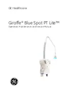
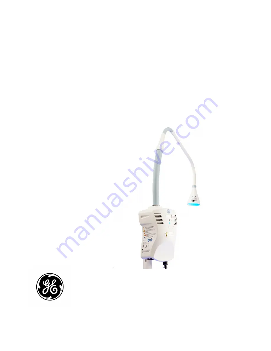
Page 1: ...Giraffe Blue Spot PT Lite Operation Maintenance and Service Manual GE Healthcare ...

Page 2: ...y All other company and product names mentioned may be trademarks of the companies with which they are associated Warranty This product is sold by GE Healthcare with a period of 12 month of GE depot repair warranty that covers labor and parts except for the LED Module assembly which has a 24 month warranty and the expendable parts like fan which have a 30 day warranty under the terms and condition...

Page 3: ...Connections 14 Chapter 2 Product Setup and Operation 17 2 1 Pre use Checkout Procedure 17 2 2 Operation 19 Chapter 3 Operator s Maintenance 23 3 1 Cleaning and Maintenance 23 3 2 Options 25 Chapter 4 Operator Troubleshooting 27 Chapter 5 Specifications 29 5 1 Electrical Specifications 29 5 2 Environmental Specifications 29 5 3 Performance Specifications 30 5 4 Standards 31 Part II Service 33 Impor...

Page 4: ... 10 2 Test Points and Adjustment Point Locations 62 Chapter 11 Replacement Procedures 63 11 1 Air Filter Replacement 64 11 2 Fuse Replacement 64 11 3 Light Pipe O ring Ground Clip Replacement 65 11 4 Light Shade Replacement 66 11 5 Unit Cover Control Board Replacement 67 11 6 Power Inlet Module AC and DC Harness Replacement 68 11 7 LED Module LED Driver Board Fan Replacement 69 11 8 Power Supply R...

Page 5: ... operated by personnel trained in its operation and familiar with the risks and benefits of this type of device Conventions Various types of pictures or icons are used in this manual wherever they reinforce the printed message to alert you to potential safety hazards in one of the following ways WARNING A WARNING statement is used when the possibility of injury to the patient or the operator exist...

Page 6: ...ne or written request for service advice be made to the nearest GE Healthcare Regional Service Center This Product or any of its parts should not be repaired other than in accordance with written instructions provided by GE Healthcare and by GE Healthcare trained personnel The Product must not be altered without the prior written approval of GE Healthcare s Quality Assurance Department The user of...

Page 7: ... 7 Part I Operation and Maintenance ...

Page 8: ...8 Part I Operation and Maintenance This page is intentionally left blank ...

Page 9: ...ls of infants receiving phototherapy according to hospital policy and procedure WARNING All phototherapy methods have possible risks including but not limited to bronze baby syndrome diarrhea loose green stool hyperpigmentation reddening skin blistering oxidative tissue damage skin irritation rashes water loss and dehydration Monitor the baby closely for signs of these conditions during photothera...

Page 10: ...armers or heated mattresses and may raise the patient s body temperature Always monitor the infant s temperature and make the appropriate adjustments to these devices to avoid temperature fluctuations during phototherapy WARNING Using reflective foils to increase the efficacy of phototherapy may cause hazardous patient body temperatures WARNING Oxygen enriched environments greatly reduce the tempe...

Page 11: ...ria Concomitant use of drugs or agents that are photosensitive Concurrent therapy with metalloporphyrin heme oxygenase inhibitors Phototherapy effectiveness may be decreased in presence of cholestasis direct hyperbilirubinemia MacDonald Ramasethu 2007 Atlas of Procedures in Neonatology Lippincott Williams Wilkins Philadelphia PA Symbol Definitions This section identifies the symbols that are displ...

Page 12: ...e light shade to the patient This symbol indicates that the waste of electrical and electronic equipment must not be disposed as an unsorted municipal waste and must be collected separately Please contact an authorized representative of the manufacturer for information concerning the decommissioning of your equipment ...

Page 13: ...herapeutic light and a red indicator will flash if the fan fails to operate correctly or the device overheats The red indicator will illuminate continuously while the fan operates if the device is too cold The fan will operate in an attempt to cool or warm the system into the proper operating temperature Underneath on the base of the device are the IEC power inlet two fuses potential equalization ...

Page 14: ...Fuses Compartment 11 Intake vents air filter 12 Potential equalization stud 13 Light pipe port 14 Light shade protective cover To isolate the device from the supply mains For a wall connected device unplug the power cord For a device connected to a microenvironment s accessory outlet switch off the mains switch on the back of the microenvironment 1 2 3 4 5 6 7 FRONT BACK BOTTOM 8 13 14 12 11 9 10 ...

Page 15: ...by or emitting light The number represents the number of hours the device has been emitting light during the the life of the device Over under temperature indicator Off No temperature problems detected Steady red Under temperature condition Flashing red Over temperature condition The over under temperature red indicator briefly flashes every time the Standby On switch is depressed to turn on the t...

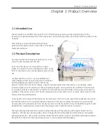
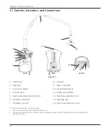
Page 16: ...This page is intentionally left blank 16 Chapter 1 Product Overview ...

Page 17: ... including power cord light pipe light box and labels If damage is found do not use the device and contact service personnel 2 Check that the light box is securely attached to the accessory dovetail rail or roll stand i e the device does not slide up or down the dovetail rail 3 Move the light pipe to verify that it moves freely and stays in position NOTE The light pipe will typically experience so...

Page 18: ... 3 5 Figure 2 1 Light Measurement Points 10 Divide the lowest reading by the highest reading If the LED light is functioning properly the result should be greater than 0 4 If the result is not greater than 0 4 contact service NOTE IEC standards recommend LED module replacement at 25 output reduction which corresponds to 27 μW cm 2 nm 1 and occurs at approximately 10000 hours However sufficient irr...

Page 19: ...erapy WARNING Phototherapy light can affect the temperature in the thermoregulation devices incubators radiant warmers or heated mattresses and may raise the patient s body temperature Always monitor the infant s temperature and make the appropriate adjustments to these devices to avoid temperature fluctuations during phototherapy WARNING Using reflective foils to increase the efficacy of photothe...

Page 20: ...et rolls or positioning aids that block the light source 4 If the system is mounted on a portable roll stand lock the wheels to prevent the movement of the device during the therapy 5 Press the standby on switch to turn on the therapeutic light 6 Position the light shade at 38cm from the infant and aim the light towards the infant The spot diameter will be 35 5cm 7 Using a calibrated Biliblanket L...

Page 21: ...OTE It is recommended to monitor irradiance according to hospital policy and procedure during phototherapy NOTE The efficacy of phototherapy depends on the light intensity patient surface coverage area distance and light spectrum of the phototherapy device use 21 Chapter 2 Product Setup and Operation ...

Page 22: ...This page is intentionally left blank 22 Chapter 2 Product Setup and Operation ...

Page 23: ...cies 1 Unplug the power cord and allow the system to cool at least 10 minutes before cleaning 2 Clean the clear protective cover of the light shade using a non flammable optical cleaner 3 Clean the outside of the light box light pipe and light shade using a cleaning solution listed in section 3 1 2 Aqueous solutions which are both hospital disinfectants and microbactericides may be used Do not all...

Page 24: ...ommendations will greatly extend the life of the parts NOTE Any parts cleaned with iodophor solution will stain yellow 3 1 3 Factors that affect product life Factor Description Thermal stress Operating without the cooling fan running or operating with clogged filters will reduce LED life Light pipe folding or excessive bending Do not fold or bend the light pipe any tighter than 60 degrees NOTE To ...

Page 25: ...iginally supplied with the system shall be applied to the the light pipe and the port to protect the therapeutic light LED and fiber against dust and dirt CAUTION Do not fold the light pipe or bend it tighter than 60 degrees to avoid light pipe damage 3 2 Options Portable Roll Stand 6600 0894 216 GE Healthcare BiliBlanket Meter II 6600 0198 900 NOTE Use only GE approved optional parts with the dev...

Page 26: ...This page intentionally left blank 26 Chapter 3 Operator s Maintenance ...

Page 27: ...s an hour number Power cord is not properly connected Confirm that the power cord is plugged into the power outlet and power inlet module Also make sure that the power cord is secured by the retainer clip OS2 When the system is plugged into the power outlet the over under temperature indicator is illuminated in steady red The system temperature is low under temperature condition Make sure the syst...

Page 28: ... under temperature indicator will also turn off and the standby on indicator will illuminate green This process may take several minutes OS4 The system generates low light output less than 27 µW cm 2 nm 1 on average Protective cover of light shade is dirty Clean the cover gently using cleaning solution and a lint free wipe Wrong light meter is used for light output measurement Make sure that the r...

Page 29: ... on the back of the microenvironment 5 2 Environmental Specifications 5 2 1 Operating Conditions Ambient Temperature 18 to 30 C Relative Humidity 10 to 95 non condensing Atmospheric Pressure 64 kPa to 106 kPa Equipment not suitable for use in presence of flammable anaesthetic mixture with air or with oxygen or nitrous oxide IPX0 Not protected from water ingress 5 2 2 Transport and Storage Conditio...

Page 30: ... can be extended as long as service parts are available IEC standards recommend LED replacement at 25 output reduction which occurs at approximately 10000 hours However sufficient irradiance for effective phototherapy continues well after 25 reduction AMERICAN ACADEMY OF PEDIATRICS Subcommittee on Hyperbilirubinemia Clinical Practice Guideline Management of Hyperbilirubinemia in the Newborn Infant...

Page 31: ...EC 60601 1 CAN CSA C22 2 60601 1 IEC 60601 2 50 GE Healthcare a division of General Electric has declared that this product conforms with the European Council Directive 93 42 EEC Medical Device Directive when it is used in accordance with the instructions provided in the Operation and Maintenance Manual Distance H cm Surface Area A cm2 Average Total Irradiance for Bilirubin mW cm 2 38 990 2 94 50 ...

Page 32: ...This page intentionally left blank 32 ...

Page 33: ... 33 Part II Service ...

Page 34: ...34 Part II Service This page is intentionally left blank ...

Page 35: ...n only without warranty of the results with respect to any application of such information Furthermore because of the wide variety of circumstances under which maintenance and repair activities may be performed and the unique nature of each individual s own experience capacity and qualifications the fact that a customer has received such information from GE Healthcare does not imply in any way tha...

Page 36: ...а е налично само на английски език Ако доставчикът на услугата на клиента изиска друг език задължение на клиента е да осигури превод Не използвайте оборудването преди да сте се консултирали и разбрали упътването за работа Неспазването на това предупреждение може да доведе до нараняване на доставчика на услугата оператора или пациентa в резултат на токов удар механична или друга опасност 警告 本维修手册仅提...

Page 37: ...níka prodejního servisu obslužného personálu nebo pacientů vlivem elektrického proudu respektive vlivem mechanických či jiných rizik ADVARSEL Denne servicemanual findes kun på engelsk Hvis en kundes tekniker har brug for et andet sprog end engelsk er det kundens ansvar at sørge for oversættelse Forsøg ikke at servicere udstyret uden at læse og forstå denne servicemanual Manglende overholdelse af d...

Page 38: ...laan vahingoittuminen sähköiskun mekaanisen vian tai muun vaaratilanteen vuoksi ATTENTION Ce manuel d installation et de maintenance est disponible uniquement en anglais Si le technicien d un client a besoin de ce manuel dans une langue autre que l anglais il incombe au client de le faire traduire Ne pas tenter d intervenir sur les équipements tant que ce manuel d installation et de maintenance n ...

Page 39: ...elmen kívül hagyása a szolgáltató működtető vagy a beteg áramütés mechanikai vagy egyéb veszélyhelyzet miatti sérülését eredményezheti AÐVÖRUN Þessi þjónustuhandbók er aðeins fáanleg á ensku Ef að þjónustuveitandi viðskiptamanns þarfnast annas tungumáls en ensku er það skylda viðskiptamanns að skaffa tungumálaþjónustu Reynið ekki að afgreiða tækið nema að þessi þjónustuhandbók hefur verið skoðuð o...

Page 40: ... rasties elektriskās strāvas trieciena mehānisku vai citu faktoru izraisītu traumu risks apkopes sniedzējam operatoram vai pacientam ĮSPĖJIMAS Šis eksploatavimo vadovas yra tik anglų kalba Jei kliento paslaugų tiekėjas reikalauja vadovo kita kalba ne anglų suteikti vertimo paslaugas privalo klientas Nemėginkite atlikti įrangos techninės priežiūros jei neperskaitėte ar nesupratote šio eksploatavimo...

Page 41: ...o pode ocasionar ferimentos no técnico operador ou paciente decorrentes de choques elétricos mecânicos ou outros ATENÇÃO Este manual de assistência técnica só se encontra disponível em inglês Se qualquer outro serviço de assistência técnica solicitar este manual noutro idioma é da responsabilidade do cliente fornecer os serviços de tradução Não tente reparar o equipamento sem ter consultado e comp...

Page 42: ...nje ovog upozorenja može dovesti do povređivanja servisera rukovaoca ili pacijenta usled strujnog udara ili mehaničkih i drugih opasnosti UPOZORNENIE Tento návod na obsluhu je k dispozícii len v angličtine Ak zákazníkov poskytovateľ služieb vyžaduje iný jazyk ako angličtinu poskytnutie prekladateľských služieb je zodpovednosťou zákazníka Nepokúšajte sa o obsluhu zariadenia kým si neprečítate návod...

Page 43: ...tar hänsyn till den här varningen kan det resultera i skador på serviceteknikern operatören eller patienten till följd av elektriska stötar mekaniska faror eller andra faror DİKKAT Bu servis kılavuzunun sadece ingilizcesi mevcuttur Eğer müşteri teknisyeni bu kılavuzu ingilizce dışında bir başka lisandan talep ederse bunu tercüme ettirmek müşteriye düşer Servis kılavuzunu okuyup anlamadan ekipmanla...

Page 44: ...44 Important Service Safety Information This page is intentionally left blank ...

Page 45: ...ent recirculation The fan is installed in a certain position to pull air from the lower chamber cool zone to the upper chamber hot zone Backward installation of the fan causes reverse air flow from hot zone to cool zone and negatively impacts the heat sink cooling During over temperature under temperature conditions the fan keeps running to bring the LED assembly temperature to the ambient tempera...

Page 46: ...r is on continuously during under temperature conditions and flashes repeatedly during over temperature conditions Power supply board The system includes a universal switching power supply board that can accept AC input voltages in the range of 90 264 VAC at frequency range of 47 63 Hz to generate 12 VDC output that feeds the LED driver board Power input connection and fuses The power cord connect...

Page 47: ... light box as described in section 7 4 1 7 1 Time Required for Installation The average installation time for the Giraffe Blue Spot PT Lite is about 5 minutes The required checkout procedures after installation take approximately 20 minutes 7 2 Environmental Requirements The system shall be installed serviced and operated within the environmental conditions described in section 5 2 7 3 Tool Requir...

Page 48: ...efer to Figure 7 1 3 Remove the plastic protective caps of the light pipe and the light pipe port Remove the plastic protective sleeve of the light pipe mounting clip 4 Insert the light pipe tip into the light pipe port until the clip is aligned to the top mounting screw hole Refer to Figure 7 2 5 Use the hex key to reinstall the top mounting screw Figure 7 1 Figure 7 2 48 Chapter 7 Installation ...

Page 49: ...key to tighten the two mounting screws Refer to Figure 7 4 Note If you intend to plug the power cord into an accessory outlet on a microenvironment refer to the microenvironment manual for proper power cord connection 5 Plug the power cord into the power inlet connector and rotate the retainer to grip and secure the power cord and then plug it into the power outlet NOTE If you intend to plug the p...

Page 50: ...This page is intentionally left blank 50 Chapter 7 Installation ...

Page 51: ...me Average Time in Minutes Performed as Planned Maintenance Performed as Checkout after any Service 8 4 1 Visual Inspection 5 Annually Yes 8 4 2 Functional Checks 5 Annually Yes 8 4 3 Light Intensity Check 5 Annually Yes 8 4 4 Electrical Safety Tests 5 Annually Yes Service includes installation repair maintenance or part replacement WARNING Do not service the Giraffe Blue Spot PT Lite while it is ...

Page 52: ... evident and perform electrical safety test as instructed in section 8 4 4 3 Check that the power cord retainer is in place 4 Examine the system overall for any damaged cracked or broken or missing parts such as the plastic unit cover standby on switch standby on indicator over under temperature indicator hour meter display light pipe light shade air filter guard or potential equalization stud If ...

Page 53: ...RNING Never look directly at the light Exposure can cause eye damage 8 4 3 Light Intensity Check In order to ensure uniform light distribution and the performance of all the optical components perform the following procedure 1 Turn on the system 2 Focus the light so that the spot diameter is 35 5 cm 14 or when the shade is 38 cm 15 from the bed surface 3 Using a calibrated Biliblanket Light Meter ...

Page 54: ...gged into an accessory outlet on a microenvironment measure the resistance between the power cord ground terminal of the microenvironment and the potential equalization stud on the Giraffe Blue Spot PT Lite The ground resistance must be less than 0 2 ohms 8 4 4 2 Leakage Current Checks In normal conditions and in all possible operating modes For a system plugged into a wall outlet measure the leak...

Page 55: ...Chapter 9 Calibration No calibration is required for the Giraffe Blue Spot PT Lite 55 ...

Page 56: ...This page is intentionally left blank 56 Chapter 9 Calibration ...

Page 57: ...hapter 11 Always read all the warnings cautions notes and other information provided in the Important Service Safety Information before starting any troubleshooting NOTE For each symptom the possible causes are listed in a certain sequence to provide a quick and effective troubleshooting guide Therefore investigate the possible causes of each symptom in order from top to bottom to find the root ca...

Page 58: ...r and then re measure voltage at the harness connectors If the voltage is now within the range replace the LED drive board Refer to section 11 7 Otherwise remove the LED driver board and a disconnect the DC harness from the power supply board and perform the wire continuity test on the harness to confirm the harness is not defective Replace the DC harness if necessary b with the DC harness disconn...

Page 59: ... system has warmed up to the ambient temperature the system fan will turn off the over under temperature indicator will turn off and the standby on indicator will illuminate green This process may take several minutes Thermistor wire harness is unplugged Remove the unit cover and check whether the thermistor wire is plugged into its corresponding connector on LED driver board Also confirm that the...

Page 60: ...ower outlet Remove the light pipe and look into the light pipe port to confirm no object is blocking the light output LED anode or cathode cables connections are reversed or unplugged Remove the unit cover and check whether the anode and cathode cables are unplugged or reversed Make proper connections if necessary Refer to section 11 7 The control harness is defective Remove the control harness an...

Page 61: ... diameter is 35 5 cm 14 or the shade is 38 cm 15 from the bed surface and the light is aiming at the bed surface Light pipe is defective or LED module is defective or reached end of life Contact service S12 The system generates nonuniform light output distribution the lowest to highest reading ratio is less than 0 4 Protective cover of light shade is dirty or heavily scratched Clean the cover or r...

Page 62: ...ut Part Description 1 V test point LED driver board 2 GND test point LED driver board 3 12V test point LED driver board 4 Fan test point LED driver board 5 Fan test point LED driver board 6 R13 potentiometer adjustment point power supply board Note Test points and adjustment point are used for diagnostics and troubleshooting purposes 1 2 3 4 5 6 ...

Page 63: ...autions notes and other information provided in Important Service Safety Information before starting any replacement or repair All replacement and repair procedures shall be performed by authorized service personnel only CAUTION Always perform electrical safety test after any replacement procedure NOTE Standard service tools such as a pair of small pliers screwdrivers and nut drivers and the provi...

Page 64: ...stem power cord is unplugged from the power outlet 2 Release the power cord retainer to unplug the power cord from the system 3 Use a flat head screwdriver to open the fuse compartment lid of the power inlet module and pull the compartment out to access the fuses Refer to Figure 11 2 4 Remove the fuses 5 Replace these fuses with the two fuses T3 15A 250V slo blo type in fuse kit 6600 0730 214 6 Re...

Page 65: ...p to the device and detach the light pipe Refer to Figure 11 4 4 To remove the O rings rotate the light pipe while pulling out the O rings 5 To remove the ground clip hold the light pipe end close to the clip firmly and then use a pair of long nose or pliers to pull out the clip 6 Reverse steps to re install CAUTION The LED light output is susceptible to dust and dirt When the light pipe is detach...

Page 66: ... which shows the shade with orange tape removed 3 Use a pair of small pliers or any appropriate tool to grip and remove the plastic pin to release the shade Refer to Figure 11 6 NOTE When replacing the light shade make sure to not touch the fiber Residual dirt or grease on the fiber can decrease the light output 4 Reverse steps to re install Figure 11 5 Figure 11 6 66 Chapter 11 Replacement Proced...

Page 67: ...iner to unplug the power cord from the system 4 Use a Philips screwdriver to remove the back plate screws Refer to Figure 11 7 5 Slide off the unit cover gently until the control board harness is accessible and disconnect the harness from the LED driver board Refer to Figure 11 8 6 To remove the control board use a Philips screwdriver to remove the control board screws and pull out the fish paper ...

Page 68: ...r module Refer to Figure 11 9 Note how AC wires are connected to power module terminals before unplugging them to avoid wrong connections during re installment 6 Use a Philips screwdriver to remove the power inlet module screws and pull the module out 7 To remove the AC harness disconnect the AC harness from the power supply board To remove the AC harness ground wire use a 7 mm nut driver to remov...

Page 69: ...e that static charges are safely conducted to the ground and not through the sensitive device to prevent damage to the equipment 1 Make sure the system power cord is unplugged from the power outlet 2 Remove the unit cover as instructed in section 11 5 3 Disconnect the LED anode and cathode wires from the LED driver board and pull them away from the baffle Refer to Figure 11 11 4 Disconnect the the...

Page 70: ...ontains the LED module with a new fan attached to it 8 To remove the fan use a Philips screwdriver to remove the fan screws to release the fan Refer to Figure 11 14 9 Reverse the steps to re install NOTE When re installing the fan make sure that the arrow symbol on the top side of the fan points towards the heat sink to avoid backward installation Refer to Figure 11 15 Furthermore to re install th...

Page 71: ... ground and not through the sensitive device to prevent damage to the equipment 1 Make sure the system power cord is unplugged from the power outlet 2 Remove the unit cover as instructed in section 11 5 3 Remove the LED driver board as instructed in section 11 7 4 Use a 5 5mm nut driver to remove the nuts that attach the power supply board to the back plate to release it 5 Reverse steps to re inst...

Page 72: ...This page is intentionally left blank 72 Chapter 11 Replacement Procedures ...

Page 73: ...s the Giraffe Blue Spot PT Lite service parts and includes the orderable service kit component part numbers A complete Field Replaceable Unit FRU list and a wiring diagram are also provided The illustrations and part numbers begin on the next page 73 ...

Page 74: ...12 1 Illustrated Parts Figure 12 1 Light Box Exploded View 9 10 11 12 hidden 13 14 4 1 7 3 6 5 2 8 21 22 hidden 20 19 18 17 16 15 23 74 Chapter 12 Service Parts ...

Page 75: ...3160 001 Cover FRU Kit Estonian 2063162 001 Cover FRU Kit Indonesian 2063164 001 Cover FRU Kit Latvian 2063166 001 Cover FRU Kit Serbian 2063168 001 Cover FRU Kit Slovakian 2063926 001 Cover FRU Kit croation 2 LED module M1225811 LED Module FRU Kit 3 Back plate Non orderable Non orderable 4 Screw M4 M1225820 Hardware FRU Kit or Cover FRU Kit 5 Power entry module 2065981 001 Power Entry Module FRU ...

Page 76: ...t 18 Nut M3 Nylok M1225820 Hardware FRU Kit 19 Spacer nylon 0 14 ID 0 125 LG M1225820 Hardware FRU Kit 20 Rubber washer M1225820 Hardware FRU Kit 21 Cable tie M1225820 Hardware FRU Kit 22 Clip mount M1225820 Hardware FRU Kit 23 Washer M4 External tooth M1225820 Hardware FRU Kit or Cover FRU Kit This part can be ordered as part of Cover FRU Kit too See callout 1 for Cover FRU Kit part numbers 76 Ch...

Page 77: ...M1225812 or 2075264 001 Light Pipe FRU Kit or Grounding Clip FRU kit 3 O RING Dash 022 EP M1225812 or M1226989 Light Pipe FRU Kit or Light pipe O ring FRU kit This service kit contains a light pipe with an attached light shade grounding clip and already lubriacted O rings To see contents of the service kit or Light pipe O ring FRU kit refer to section 12 4 2 77 Chapter 12 Service Parts ...

Page 78: ...ce Part Number Orderable Service Part Description 1 Sleeve shade M1225813 Light Shade FRU Kit 2 Tape orange M1225813 Light Shade FRU Kit 3 Retention pin shade M1225813 Light Shade FRU Kit 4 Light shade M1225813 Light Shade FRU Kit 1 3 2 4 78 Chapter 12 Service Parts ...

Page 79: ...1225820 Control Board FRU Kit or Hardware Kit 4 Harness Control M1225817 Harness FRU Kit 5 Switch cap See Note See Note 6 Control harness ferrite M1225817 Harness FRU Kit 7 Fish paper M1225814 Control Board FRU Kit Note Swtich cap is a component of the unit cover kit Refer to the table corresponding to Figure 12 1 for unit cover kit part numbers and section 12 4 2 to see service kit contents 2 1 3...

Page 80: ...225811 or M1225817 LED Module FRU Kit or Harness FRU Kit 5 Baffle M1225811 LED Module FRU Kit 6 Fan M1225811 or M1236301 LED Module FRU Kit or Fan FRU Kit 7 LED harness anode and cathode ferrite M1225817 or M1225811 Harness FRU Kit or LED Module FRU Kit Anode Cathode harnesses are also orderable through Harness FRU Kit Refer to Figure 12 7 and section 12 4 2 to see the kit contents Fan is also ord...

Page 81: ...rness FRU Kit 4 Power entry module 2065981 001 Power Entry Module FRU Kit 5 AC harness hot neutral M1225817 Harness FRU Kit 6 AC harness ground M1225817 Harness FRU Kit 7 Hex Nut M4 with tooth washer M1225820 Hardware FRU Kit 8 Nut M3 Nylok M1225820 or M1226990 Hardware FRU Kit or Power supply FRU Kit 9 Spacer Nylon 0 14 ID x 0 25 LG M1225820 or M1226990 Hardware FRU Kit or Power supply FRU Kit 10...

Page 82: ...ure 12 7 Harnesses Callout Part Description Orderable Service Part Number Orderable Service Part Description 1 LED Ground Harness M1225817 Harness FRU Kit 2 Thermistor Harness 3 DC Harness 4 Anode Red 5 Cathode Black 6 Control Harness 7 AC Harness 1 2 3 4 5 6 7 82 Chapter 12 Service Parts ...

Page 83: ...fe brand label 3 Warning Label Non orderable Non orderable 4 Serial Number Label Non orderable Non orderable 5 Date of Manufacture Label Non orderable Non orderable 1 2 3 3 4 3 5 3 Warning labels are not orderable Order an appropriate cover FRU Kit see Figure 12 1 to get a new unit cover with a language specific warning label attached to it 83 Chapter 12 Service Parts ...

Page 84: ...tration purposes only The content on the labels shown here may be slightly different from the content of the actual labels on the system NOTE Warning labels are not orderable Order appropriate cover FRU Kit Label Description Part Number Part Description M1231816 GE Logo Label M1229489 Giraffe Brand Label Non orderable Non orderable Order an appropriate Cover FRU Kit see Figure 12 1 to get a new un...

Page 85: ... cord Denmark M1171635 Power cord Switzerland M1233858 Power cord India 2064615 001 Power cord Philippines M1233860 Power cord Israel M1231502 Power cord IEC M1233855 Power cord Japan M1236635 Power cord Italy 12 4 FRU List 12 4 1 Spare Parts Components Service Part Number Service Part Description 6600 0714 200 Touchup paint light gray M1231816 GE Logo Label M1229489 Giraffe Brand Label M1231448 H...

Page 86: ...h 022 EP lubricated 3 Grounding Clip 1 M1225813 Light Shade FRU Kit Light Shade 1 Pin retention shade 2 Orange Tape 1 Sleeve shade 1 Output Reflector 1 M1225814 Control Board FRU Kit PCBA Control board 1 Screw M3 8MM LG 3 LCD cover 1 Fish Paper 1 M1225816 Air Filter FRU Kit Filter foam 1 Filter guard 1 M1225817 Harness FRU Kit Harness AC 1 Harness DC 1 Harness Control with Ferrite 1 Harness Thermi...

Page 87: ...AP 3 Washer M3 External TOOTH 7 Washer M4 External TOOTH 7 Washer Rubber 4 Washer 14 5010 1 Clip mount 1 Cable tie 1 Spacer nylon 0 14 ID x 0 25 LG 4 Spacer 0 14 ID 0 125 LG 8 Screw M3 16MM LG PAN HD MACH 2 Potential equalization terminal 1 M1226989 Light pipe O ring FRU Kit O ring dash 022 EP lubricated 3 M1226990 Power Supply FRU Kit Power supply 100W 1 Nut M3 NYLOK 4 Spacer Nylon 1 4 4 M1236301...

Page 88: ...12 5 Wiring Diagram 88 Chapter 12 Service Parts ...

Page 89: ...ion provided in this appendix WARNING Portable and mobile RF communication equipment can affect Medical Electrical Equipment Caution should be used when operating such devices around Medical Electrical Equipment WARNING This equipment system is intended for use by healthcare professionals only This equipment system may cause radio interference or may disrupt the operation of nearby equipment It ma...

Page 90: ...raffe Blue Spot PT Lite uses RF energy only for its internal function Therefore its RF emissions are very low and are not likely to cause any interference in nearby electronic equipment RF emissions CISPR 11 Class A The Giraffe Blue Spot PT Lite is suitable for use in all establishments other than Domestic and those directly connected to the public low voltage power supply network that supplies bu...

Page 91: ...e 2kV common mode line Mains power quality should be that of a typical commercial or hospital environment Voltage dips shorts interruptions and voltage variations on power supply input lines IEC 61000 4 11 5 Ut 95 dip in Ut 0 5 cycle 40 Ut 60 dip in Ut for 5 cycles 70 Ut 30 dip in Ut for 25 cycles 5 Ut 95 dip in Ut for 5 sec 5 Ut 95 dip in Ut 0 5 cycle 40 Ut 60 dip in Ut for 5 cycles 70 Ut 30 dip ...

Page 92: ... 150 KHz to 80 MHz 3V d 1 2 P Radiated RF IEC 61000 4 3 3 V m 80 MHz to 2 5 GHz 3 V m IEC 60601 2 19 IEC 60601 2 21 3 V m 26 MHz to 1 GHz 3 V m normal operation d 1 2 P 26 MHz to 800 MHz 10 V m 26 MHz to 1 GHz 10 V m no hazard d 2 3 P 800 MHz to 2 5 GHz where P is the maximum output power rating of the transmitter in watts W according to the transmitter manufacturer and d is the recommended separa...

Page 93: ...netic environment in which radiated RF disturbances are controlled The customer or the user of the Giraffe Blue Spot PT Lite can help prevent electromagnetic interference by maintaining a minimum distance between portable and mobile RF communications equipment transmitters and the Giraffe Blue Spot PT Lite as recommended below according to the maximum output power of the communications equipment R...

Page 94: ...This page intentionally left blank 94 ...

Page 95: ......

Page 96: ...ghai GE China Hi tech Park No1 Huatuo Road Zhangjiang Hi tech Park Pudong Shanghai P R China 201203 上海GE中国科技园 地址 中国上海市浦东张江高科技园华佗路1号 201203 Tel 8621 38777888 Fax 8621 38777402 Australia 1300 722 229 China 800 810 8188 India 1 800 425 7255 Korea 02 1544 4564 South Eastern Asia 65 6277 3444 Brazil Only GE Healthcare Clinical Sytems Equipamentos Médicos Ltda Av Paulista 37 13º andar CEP 01311 902 Cerq...

Reviews: