T
ROUBLESHOOTING
REV7
/REV2
OI 250 (EN)
8.2.4
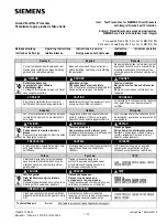
Replacing the Motor Limit Switch and/or the Auxiliary Switch
• Disconnect the wire connections to the motor limit switch (7) and/
or the auxiliary switch (5).
• Remove the locking clamps (3). Remove the drive rod
(2 or 6) and the connecting rod (4).
• Unscrew the M5 mounting screws.
• Remove the motor limit switch or auxiliary switch.
• Unscrew the M4 screw(s) and remove the lever (1).
• Mount the lever on the new motor limit switch or auxiliary switch.
1
Lever
-
2
Drive rod
-
3
Locking clamp
-
4
Connecting rod
-
5
Auxiliary switch
-
6
Drive rod
-
7
Motor limit switch
-
1 2
3
4
7
1
3
5
6
Summary of Contents for GL 311 F3/4031 P/VE
Page 2: ......
Page 10: ...INTRODUCTION 10 146 OI 250 EN REV7 REV6...
Page 12: ...SAFETY 12 146 OI 250 EN REV7 REV3...
Page 48: ...INSTALLATION 48 146 OI 250 EN REV7 REV7...
Page 80: ...INSPECTION AND MAINTENANCE 80 146 OI 250 EN REV7 REV3...
Page 102: ...RECONDITIONING 102 146 OI 250 EN REV7 REV7...
Page 104: ...END OF LIFE MANAGEMENT 104 146 OI 250 EN REV7 REV2a...
Page 114: ...SPECIAL EQUIPMENT OPTIONAL 114 146 OI 250 EN REV7 REV0...
Page 128: ...REPLACEMENT PARTS AND ACCESSORIES 128 146 OI 250 EN REV7 REV6...
Page 130: ...HANDLING USED SULFUR HEXAFLUORIDE 130 146 OI 250 EN REV7 REV2...


