background image


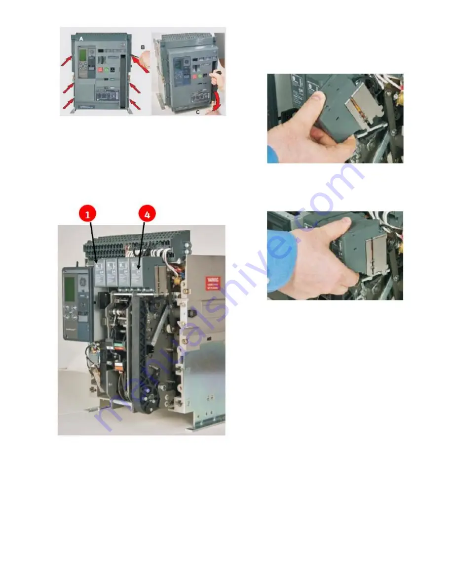
Figure 1. (A) Front Cover (B) Screw Removal (C) Handle 
Rotation 

4. This accessory is mounted on the mechanism 
top plate at 1st or 4th location as shown in 
Figure 2. 


Figure 2. 

5. Tilt the coil forward and engage the front 
hooks into the mechanism top support plate as 
shown in Fig. 3. Tilt the device backwards until 
the  

rear hooks engage in the slots on the 
mechanism top support plate as shown in Fig. 4. 


Figure 3. Shunt Trip Inserting 


Figure 4. Shunt Trip Assembly 


6. After installing the shunt release on the 
mechanism top plate, connect the input wire 
assembly plug to the A5/A6 (if installed in the first 
location) or A12/A13 (if installed in the fourth 
location) locations marked on the secondary 
disconnect as shown in Fig. 5. 


Summary of Contents for GSTG024D

Page 1: ...240V 220 240V Momentary GSTG250D 250V Continuous Momentary Rated shunt trip requires wiring one or more NO Normally Open breaker aux contact s in series with the accessory to avoid coil damage Use the following procedure to install the Shunt Trip accessory into the circuit breaker 1 Verify that the rating on the Shunt Trip Mechanism identification plate matches the voltage rating required for the ...

Page 2: ...s shown in Fig 3 Tilt the device backwards until the rear hooks engage in the slots on the mechanism top support plate as shown in Fig 4 Figure 3 Shunt Trip Inserting Figure 4 Shunt Trip Assembly 6 After installing the shunt release on the mechanism top plate connect the input wire assembly plug to the A5 A6 if installed in the first location or A12 A13 if installed in the fourth location location...

Page 3: ...e pad lock features of the breaker Figure 6 10 Fasten the 6 mounting screws of the fascia with the housing using a Pozidrive screwdriver Apply torque of 6Nm 4 42 ft lbs 11 When installing a GSST shunt trip device you must wire one or more Normally Open NO breaker auxiliary contact s in series with the shunt trip accessory coil In some cases multiple contacts in series are required to ensure reliab...

Page 4: ...Reference GSTG type Continuously Rated Shunt Trip Connection Scheme 4 ...

Page 5: ...0VDC Two 240VDC Three GE 41 Woodford Ave Plainville CT 06062 www geindustrial com 2019 General Electric Company DEH 41411 R2 05 19 5 These instructions do not purport to cover all details or variations in equipment nor to provide contingency to be met in connection with installation operation or maintenance Should further information be desired or should particular problems arise which are not cov...

Reviews: