background image

1  

11/16/2015 


GE Appliances 

GE’s 2015 27” Top Load Washer 

HTW200ASKWW 
MTW200AMKWW 
GTW220ACKWW 
HTW240ASKWW 
GTW330ASKWW 
GTW460ASJWW 
GTW485ASJWW 
GTW485ASJWS 
GTW490ACJWW 
GTW490ACJWS 
GTW680BSJWS 

Summary of Contents for GTW220ACK_WW

Page 1: ...1 11 16 2015 GE Appliances GE s 2015 27 Top Load Washer HTW200ASKWW MTW200AMKWW GTW220ACKWW HTW240ASKWW GTW330ASKWW GTW460ASJWW GTW485ASJWW GTW485ASJWS GTW490ACJWW GTW490ACJWS GTW680BSJWS ...

Page 2: ...interpretation of this information nor can it assume any liability in connection with its use WARNING To avoid personal injury disconnect power before servicing this product If electrical power is required for diagnosis or test purposes disconnect the power immediately after performing the necessary checks RECONNECT ALL GROUNDING DEVICES If grounding wires screws straps clips nuts or washers used ...

Page 3: ...asses Steel Toe Work Boot Electrically Rated Glove and Dyneema Cut Resistant Glove Keeper Brazing Glasses Cut Resistant Sleeve s Although GE Factory Service Employees are required to use the personal protection equipment PPE listed below it is recommended for GE authorized servicers to use them as well for your own protection ...

Page 4: ... Shut down the appliance Step 5 Control discharge stored energy Step 3 Isolate the appliance Step 6 Try It Verify that the appliance is locked out Prior to disassembly of the Washer to access components GE Factory Service technicians are REQUIRED to follow the Lockout Tagout LOTO 6 Step Process ...

Page 5: ...The option to select between a warm or cold rinse Deep Fill Adds more water for larger loads Deep Rinse Removes any leftover soap residue Auto Soak Loosens stains by soaking up to 2 hours GTW460 Models Deep Fill Adds more water for larger loads Dual Action Agitator Provide gentle dual wash action Deep Rinse Removes any leftover soap residue Auto Soak Loosens stains by soaking up to 2 hours Speed W...

Page 6: ...ong X Flat Back Dryer Std Series 1 1 9 Series 2 1 9 4 24 unitized 7 27 unitized Series 3 1 9 Washer only Fuel Type Dryer E Electric G Gas P Propane Partner Type P Premium Cost color H Home Depot L Lowes S Standard C Contract Hoses M Mabe Product Type R Riser A 2 Cover Top Load B 4 Cover Top Load S Standard Stationary P Portable Engineering Color Year Partner Type Product Type Fuel Type Series 1 2 ...

Page 7: ...aracters of the serial number identify the month and year of manufacture Example LF123456S June 2015 A JAN D FEB F MAR G APR H MAY L JUN M JUL R AUG S SEP T OCT V NOV Z DEC 2024 Z 2023 V 2022 T 2021 S 2020 R 2019 M 2018 L 2017 H 2016 G 2015 F 2014 D 2013 A The letter designating the year repeats every 12 years The Model Serial ID Tag is located on the bottom edge of the lid The Mini Manual is in a...

Page 8: ...et Approximate Maximum Water Levels Impeller 26 Gallons or 13 1 2 in depth from the bottom of the basket Press and hold for 3 seconds Deep Fill to achieve Impeller Bulky setting water level is 25 gallons or 12 3 4 in depth from the bottom of the basket Agitator 26 Gallons or 12 1 2 in depth from the bottom of the basket Set to super Tests are completed with an empty basket ...

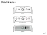
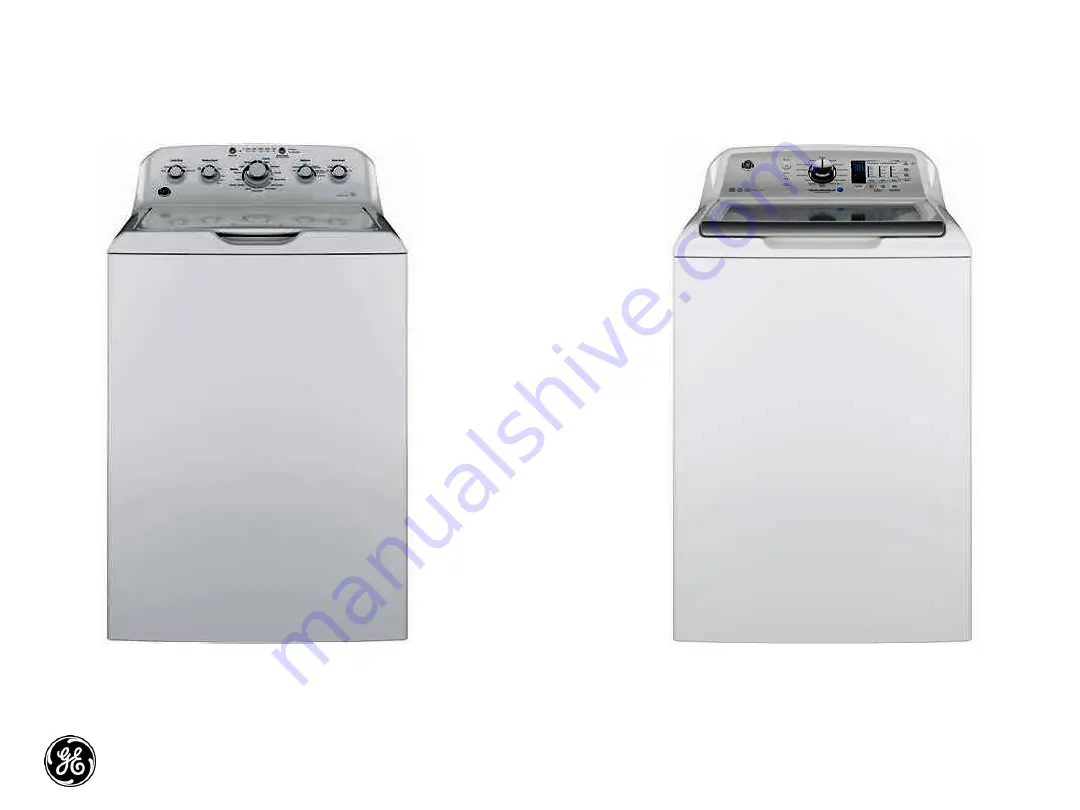
Page 9: ...9 11 16 2015 Model Graphics GTW460 GTW485 GTW490 GTW680 ...

Page 10: ...s head screws two on each side and lift lid up to remove Remove the two 1 4 in hex head screws that secure the control panel assembly to the top cover Slide the control panel assembly toward the rear of the washer to expose the hinge pin cover Hinge Pin Cover ...

Page 11: ...11 11 16 2015 Control Panel Assembly Removal To remove the control panel assembly Remove two 1 4 in hex head screws from the rear corners of the control panel ...

Page 12: ...sengage it from the top cover Roll the control panel toward the rear so the pressure tube can be seen and disconnected from the control board IMPORTANT To disengage the pressure tube from the control board grasp the tube where it connects to the pressure sensor on the board Twist the tube while pulling it off the sensor ...

Page 13: ... 4 in hex screws securing the rear panel to the control panel assembly and remove Disconnect harness from the control board IMPORTANT When reinstalling the control panel assembly ensure that all ground wires are reconnected and tested for proper continuity to the ground terminal on the power cord RJ45 Connection ...

Page 14: ...ieved without removing the top cover or disconnecting the control panel assembly completely Remove the lid assembly Disengage the control panel from the top cover and slide toward the rear to expose the hinge mounting screws Video Link ...

Page 15: ... arm by sliding it away from the hinge assembly Slide a hand between the tub cover and the top cover and grasp the hinge assembly This type hinge arm is only on the GTW680 model All the other models will have the wire form hinge ...

Page 16: ...Lid Hinge Remove the two 1 4 in hex head hinge mounting screws and remove hinge assembly from under the top cover ...

Page 17: ... into the lid lock switch assembly When a cycle is started the lock assembly engages with the striker preventing the lid from opening during the cycle The latch has spring tension on it to keep it engaged with the switch lock assembly Video Link ...

Page 18: ...Lock Striker To remove the striker from the lid Open the lid Using a small screwdriver insert it into the small hole below the striker Push inward gently on the locking tab and turn the striker to the left ...

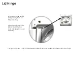
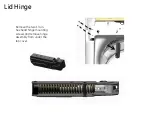
Page 19: ...Lid Lock Striker Pull the striker from the lid ...

Page 20: ... one part It requires 120 VAC to activate the lock The approximate resistance of the lock coil is 70 ohm from Red Violet from J512 board connector Checking between Red and Yellow wire at the same board connector will show the continuity of the lid switch Video Link ...

Page 21: ... lock body and then push up to remove the bezel from the top cover To remove the lid switch lock assembly Remove the bezel from the top cover by reaching under the top cover toward the lock assembly and feel for the bezel tabs the extend through the lock body Tabs ...

Page 22: ...lock assembly to the left first to disengage the right tab then slide to the right allowing the lock assembly disengage from the top cover Using a small screwdriver push down gently on the tab that prevents the lock assembly from sliding ...

Page 23: ...Lid Switch Lock Assembly Pull the lock assembly from under the top cover and disconnect the harness connector ...

Page 24: ...15 Two Coil Water Valve Remove two 1 4 in hex head screws that go through the thermistor mounting bracket into the body of the valve Turn water supply off to valve Hoses do not need to be disconnected at this time ...

Page 25: ...25 11 16 2015 Two Coil Water Valve Remove thermistor by pulling up on lip of thermistor Ensure O ring is removed with thermistor ...

Page 26: ... 11 16 2015 Two Coil Water Valve Tilt back of valve up and slide out of top cover Once valve is out and held over the basket disconnect hoses Valve and funnel are one part Gasket can be ordered separately ...

Page 27: ...27 11 16 2015 Four Coil Water Valve On GTW680 Model Video Link ...

Page 28: ...val To remove the water valve Shut off the water supply to the washer Hoses do not need to be disconnected at this time Lean the control panel assembly back It does not have to be completely removed Disconnect the harness from the water valve ...

Page 29: ...ve three 1 4 in hex head screws securing the valve to the top cover and pull the valve up Hold valve over the basket and disconnect the supply hoses from the valve There are four replaceable rubber seals that seal the water valve to the dispenser box ...

Page 30: ...2015 Thermistor Removal After the water valve is removed the thermistor can be accessed and remove It is pushed into the dispenser box and held in place by the water valve and is sealed with an O ring Thermistor ...

Page 31: ...es for the cycle selected Water is added to the dispenser from the water valve to fill and flush the cups After the valve turns off the remaining water in the cup siphons out When bleach is added to the bleach cup it is funneled through to the tub cover and into the tub Bleach Funnel Removal Video ...

Page 32: ...emoval Remove the backsplash assembly water valve and top cover Remove the dispenser tray from the dispenser body Remove four 1 4 in hex head screws from the top cover securing the dispenser body to the top cover ...

Page 33: ...ove the dispenser body from the top cover by pushing back slightly on the dispenser body and pull away from top cover The dispenser shower insert can be removed at this time for cleaning if necessary Dispenser shower insert ...

Page 34: ...34 11 16 2015 Impeller and Agitators Single Action Agitator Impeller Dual Action Agitator ...

Page 35: ...peller pop the center cap off with a small screwdriver to access the 7 16th hex bolt The splined coupler is part of the impeller and agitators Note Impeller bolt should be replaced any time it is removed for service and torqued to 100 in lbs ...

Page 36: ...l Stage Agitator To remove the dual action agitator the auger section needs to be removed to access the 7 16th hex bolt Note Agitator bolts should be replaced any time it is removed for service and torqued to 100 in lbs ...

Page 37: ...Agitator Auger Removal Feel for the small protrusion near the bottom of the auger that mounts to the agitator base Turn the top half of the auger until you feel the hole located under the auger fin lines up with the protrusion ...

Page 38: ...ugh the hole in the auger The inner wall of the agitator where the screwdriver pokes through is thin While holding the basket from spinning with one hand use the screwdriver as a leverage handle and twist the auger assembly clockwise to remove it from the agitator base Tap Screwdriver Through ...

Page 39: ...ng the agitator cap off to access the 7 16th hex bolt The bolt is located inside the agitator at the bottom A long socket extension at least 17 in long will be needed to remove it Note Agitator bolts should be replaced any time it is removed for service and torqued to 100 in lbs ...

Page 40: ...Top Cover Removal Remove the control panel assembly Slide the harness grommet out toward the rear of the washer Disengage the power cord from the top cover by pulling up on the front of the power cord grommet Pull Up ...

Page 41: ...41 11 16 2015 Top Cover Removal Slide the power cord grommet forward Slide Forward ...

Page 42: ...42 11 16 2015 Top Cover Removal Pull up off of the top cover Pull Up And Off ...

Page 43: ...e harness grommet for the lid lock does not need to be removed unless replacing the top cover If replacing the top cover squeeze the two clips on the grommet and push it through the opening Transfer to the new cover Remove ground screws ...

Page 44: ...cover Slide the harness grommet out toward the rear of the washer Disengage the power cord from the top cover by lifting up on the front of the cord grommet slide forward and up off of the top cover Raise the rear of the top cover up then pull forward slightly to disengage from the front clips that secures the front of the top cover to the cabinet ...

Page 45: ...val Remove the control panel assembly and top cover Remove the 1 5 16th in hub nut by turning the nut clock wise to loosen reverse threads A new hub nut should be used when reinstalling the basket assembly Torque to 100 ft lbs ...

Page 46: ...orque limiter WX05X10028 should be used when removing or installing the hub nut with an impact gun Remove the tub cover by unclipping eight clips around the edge and lift it off Lift the basket out of the tub Basket Removal ...

Page 47: ... the control panel assembly and top cover Disengage the rod and spring suspension from the tub assembly Prop blocks WX05X10027 x2 laying on it s side can be used under the belt protector This will raise the tub assembly up to disengage the suspension system ...

Page 48: ...acement One the suspension is disengaged remove the prop blocks letting the tub assembly rest on the belt protector Raise the cabinet up and over the tub assembly and set aside Note Be careful of the tub assembly balance while removing cabinet ...

Page 49: ...eeds to be removed to replace the harness assembly Once the cabinet is removed there are four 1 4 in hex head screws that secure the harness to the side of the tub that need to be removed There is one in hex head screw on the bottom and up to six wire ties ...

Page 50: ...and pulleys in place Recirculation Pump On some models Drive Motor Suspension Rod and Spring Assembly Drain Pump and Internal Outlet Hose Transmission Supports Assembly Mode Shifter Assembly With Clutch Harness Connectors Belt Belt Protector Motor Pulley Fan Transmission Pulley ...

Page 51: ... 3 3 8th hex head bolts The GTW680 model has a recirculation pump located at the front of the bottom of the tub It mounts to the tub the same as the drain pump Both pumps are 120 VAC The approximate resistances of the pumps checked from J512 board connector are Drain pump 13 2 ohms Recirculation pump 31 7 ohms Recirculation Pump Drain Pump Video Link Video Link ...

Page 52: ...pump only comes with one 1 hose A standard washer hose can be used for the outlet side of the pump Part number WH41X10207 Pump out as much of the standing water in the basket as possible Lean the washer back and pump out the water seen in the basket When the drain pump is removed approximately 1 2 cups of water will drain out of the pump opening in the tub Transfer Pump WX05X23817 ...

Page 53: ...53 11 16 2015 Once the bolts are removed the pump can be pulled from the tub Have something to catch excess water The seal is a separate part that can be replace if leaking Drain And Recirculation Pump ...

Page 54: ...ved easily turning the pulley to walk the belt off To reinstall the belt put it on the motor pulley first Stretch the belt around the transmission pulley as far as it can go Then rotate the pulley until the belt is in place Be sure all the ribs of the belt ...

Page 55: ...oth 120 VAC reversible motors Resistances are 1 2 hp Blue Red and Blue Yellow approx 3 1 ohm 1 3rd hp Approx 3 8 ohm from J511 board connector To remove the motor Remove the belt and fan pulley The pulley is held on by a 9 16 in lock nut Use a new nut when reinstalling the pulley and torque to 110 in lbs Disconnect the motor harness connector Push here Pull out Video Link ...

Page 56: ...ounting the motor to the tub letting the motor come loose from the platform When reinstalling the motor mounting bolts torque to 170 in lbs Hall Speed Sensor Note If the hall speed sensor is wire tied to the motor when replacing the motor Order both the motor and hall speed sensor ...

Page 57: ...clutch home position is engaged with the pulley or ready for spin It has a 120 VAC motor Resistance of the mode shift motor from Brown Blue is 5700 ohm from J512 board connector To remove the Mode shifter Remove the transmission pulley and nut The pulley is held on by a 9 16 in lock nut Use a new nut when reinstalling the pulley and torque to 110 in lbs Guide Pins ...

Page 58: ...ve two 3 8th hex head mounting bolts This will allow the complete mode shifter assembly to be removed with the clutch The clutch spring and spring washer will come off as well When reinstalling be sure to install the spring washer before the clutch spring Guide Pin Location Holes ...

Page 59: ...otor splash guard These will need to be transferred to the new platform assembly when replacing the platform transmission assembly The platform assembly is secured to the tub by eight 3 8th hex head bolts circled One of these bolts also holds one of the harness brackets to the platform Motor Shield Harness Connector Bracket Harness Connector Bracket ...

Page 60: ... 3 8th hex head bolts and pull the platform away from the tub Note The bottom of the tub can be used to pry the platform transmission assembly off of the tub The tub seal is pressed on to the platform transmission assembly If there is a leak from the seal the complete transmission will need to be replaced Triple Lip Tub Seal ...

Page 61: ... tub Press the tub seal into the tub opening Note Line the guide post with the opening in the platform Tighten the eight hex head bolts in a crisscross pattern so that the seal is pulled into the tub evenly and securely This is done by tightening each bolt about 1 4 of the way in at a time Torque to 65 in lbs Guide Post 8 7 6 5 4 3 2 1 ...

Page 62: ...62 11 16 2015 Schematic ...

Page 63: ...63 11 16 2015 Control Board User Interface J701 J511 J513 J602 J512 J101 J514 J615 J401 ...

Page 64: ...64 11 16 2015 Consumer Error Mode Entry ...

Page 65: ...65 11 16 2015 Consumer Help Indicator ...

Page 66: ...66 11 16 2015 Service Mode Entry ...

Page 67: ...67 11 16 2015 Binary Display Test and Fault Chart ...

Page 68: ...68 11 16 2015 Service Mode Tests ...

Page 69: ...69 11 16 2015 Service Mode Tests ...

Page 70: ...70 11 16 2015 Service Mode Tests ...

Page 71: ...71 11 16 2015 Service Mode Tests ...

Page 72: ...72 11 16 2015 Service Mode Tests ...

Page 73: ...73 11 16 2015 Service Mode Tests ...

Page 74: ...74 11 16 2015 Service Mode Tests ...

Page 75: ...75 11 16 2015 Service Mode Tests ...

Page 76: ...76 11 16 2015 Service Mode Tests ...

Page 77: ...77 11 16 2015 Fault Codes ...

Page 78: ...78 11 16 2015 Fault Codes ...

Page 79: ...79 11 16 2015 Fault Codes ...

Page 80: ...80 11 16 2015 Fault Codes ...

Page 81: ...81 11 16 2015 Warranty ...

Reviews: