background image

Summary of Contents for GXSF39E

Page 1: ... Models GXSF35E GXSF39E Sistema Suavizante de Agua Modelos GXSF35E GXSF39E La secci6n en espafiol empieza en la pagina 31 System tested and certified by NSF hHernational against NSF ANSI Standard 44 tbr die chemical reduction claims specified on the pert_ rmance data sheet Sistema probado y certi icado por NSF International contra norma 44 de NSF ANSI para las afirmaciones de reducci6n de los prod...

Page 2: ...m iJi Transformer must be luo _ed into indoor 120 xolt grotmded outlet only PROPER INSTALLAtiON This water softening system must be properly installed and located in accordance with the Installation Instructions before it is used _ Install or store where it will not be exposed to temperatures beh w fl eezing or exposed to any type of weather Water fi eezing in the system will break it Do not attem...

Page 3: ...daytime pressm e is over 80 psi nighttime pressm e may exceed the maximmn krse a pressm e reducing valve if necessary Adding a pressm e reducing valve Inav reduce tile flow Check local codes Tile installation must con I Ill to theI In the Commonwealth of Massachusetts Plumbing Code 248 CMR shall be adhered to Consult with your ficensed plumber Lrse only lead h ee solder and flux for all sweat sold...

Page 4: ...ect Be sure the electric outlet and transformer are in an inside location to protect from wet weather Be sure the outlet is unswit hed to prevent accidental shutolt _ If installing in an outside location you must take the steps necessary to assure the sotiene_ installation plumbing wiring etc are as well protected ti om the elements stmlight rain wind heat cold contamination wmdalism etc as when i...

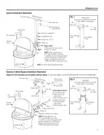
Page 5: ...l 3 Valve Bypass Installation Illustration Adapters for this installation are not supplied with the softener Toorder these adapters call GEParts800 626 2000 Askfor Part WS6OX10006 120 voltoutlet 24V transf Salt hole Softwater _ 4 _ MAI _ _ N A_ _ Hardwater to _ L _tfPIPE outsidefaucets r Bypassvalve Inlet valve _ _ 3 Valve BypassSystem Forsoft water service Openthe inlet and outlet valves Closethe...

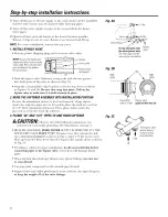
Page 6: ...h Shaq objects under the tank may puncture it If needed place the tank on a section of 3 4 thick minim urn plywood Then place shims under the plywood as needed to level the sottener 3 PLUMB IN AND OUT PIPES TO AND FROM SOFTENER a CAUTION Obser e all ot the following cautions as xou connect inlet and outlet i lumbing See illustrations on page 5 BE SURE INCOMING HARD WATER SUPPLY IS DIRECTED TO THE ...

Page 7: ...and 50 psi do not raise higher than 8 above the floor Fox inlet pressure above 50 psi the drain line may be raised to a maximum height of 14 4 4 CONNECTING A RIGID VALVEDRAIN TUBE To adapt a copper drain tube to the soflenel use a hacksaw to cut the barbed end li om the drain fitting as shown in Fig 4A Rotate the drain fitting so the cutting blade clears the valve housing to prevent damage to valv...

Page 8: ... is expelled then close NOTE If water appears chmdv or has salty taste allow to I lI lot several iUOl e minutes or tmtil clear Close all water faucets Check your plumbing work for leaks m_d fix fight away if may axe found Be sure to observe previous caution notes Turn on the gas or electric supply to the water heater Light the pilot if applicable Hg6 Tovalveinlet Groundclam From valve outlet 8 ADD...

Page 9: ...ESS NUMBER L_ _ _ I Press the MODE button tmtil _ HARDNESS arrow I_ points to HARDNESS 2 Press UP or DOX _N button to set votlr water hardness nmnber in the displa DOWN decreases the hardness wdue UP increases the hardness wllue NOTE Each press of a button changes the display by 1 between 1 and 25 Above 25 the display changes 5 at a time 25 30 35 etc Holding a button in changes the nmnbe_ at a rap...

Page 10: ...ay This infi rmation is shown in the normal xun displa This is to inform the user of the xluxnbex of days betore the salt level in the brine tank reaches I evel 0 There will be salt lett in the salt tank but it mav not be sulticient to flflly recharge the system Salt should be added at this time to avoid hard water The wflue is updated daily and whenever the SALT LEVEL wflue is changed NOTE Fox th...

Page 11: ...details Press the MODEbutton to return to the normal mn display SALT EVaL n n u u nnn UUU GEAppliances com LOST TIME SIGNAL If time is lost on the displa due to power interruption the blue indicator light will flash 4 times exerx second tmtil the present time of day is entered LOW SALT SIGNAL When the DAYS TO EMPTY drops to 15 the blue indicator light and DAYS TO EMPTYin the display will flash eve...

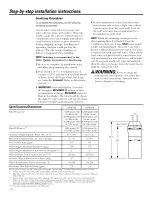
Page 12: ...ot and cold water will be fifllv soil If wm want totally soft water immediately alter the above recharge drain the water heater tmtil the water runs cold A WARNING d d i tl e water heater rise extreme care as the hot water could cause burns Turn the water heater off prior to draining Specifications Dimensions Rated Capadty Rated E liciencv Amotmt of t ig h Capacity Resin lbs cu 1 Resin Tank Nomina...

Page 13: ...ingHOTwater becausethe water heater will fill with the hard water Fill Salt dissolved in water is called brine Brine is needed to clean the hard minerals fl om resin beads To make the brine water flows into the salt storage area during the fill stage Brining Din inK brining brine travels fl om the salt storage area into the resin tank Brine is the cleaning agent needed to remove hard minerals fl o...

Page 14: ...he water softening system to work properly This small unit makes the suction to move brine fl om the salt storage area to the resin tank during recharge If it becomes i lugged with sand dirt etc the water sottening system will not work and w u will get hard water To get to the nozzle and venturi remove the water sottening system top cover Be sure the water softening system is in service cycle no w...

Page 15: ...y area Tile water sottening system begins an immediate recharge and when over in about two hours you will have a new supply of sott water Once started you cannot cancel this rechaige Feature Memory If electrical power to tile water sottening system is interi upted tile control display is blank and tile blue indicator light is otf but tile control keeps correct time fin about 6 hours When power is ...

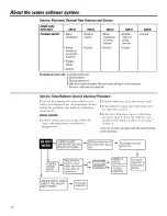
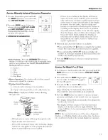
Page 16: ...st make the ti llowing visual checks VISUALCHECKS I Is there electrical power to the outlet the water softening system transli_rmer is plugged into 2 Is there sufticient salt in the storage tank 3 Is the sottener bypass wove directing water fin sott water service 4 Is the wove drain hose open to the drain not more than 8 above the sottene_ and unobst_ ucted If hose is above 8 see page 7 section 4 ...

Page 17: ...heck to make sure harness is cmmected to board properly If there is a reading in the display there may be a problem associated with the turbine Tm n off water sui i ly close the by pass wflve and disconnect by pass wflve fl om wflve body Check tm bine for binding or restriction due to debris If this does not correct tile problem the Timer Sensor or Turbine mar require replacement 4 Historical data...

Page 18: ...ge is not preventing water fl om contacting salt See Care and cleaning of the water softening system section If the water softening system does not draw brine check nozzle and or venttlri dirty or deflective N deflective nozzle and venmri seal _ nozzle and ventm i not seated properly on gasket _ other inner valve defect rotor seal rotor and disc wave washer etc _ restricted drain check drain fitti...

Page 19: ...GE reconm_ends using only Dianmnd Crystal Red Out _ brand salt Cleaning Iron Out of the Water Softening System Your water soltelfing systeln takes hardness nlinerals calciunl and inagnesiunl out of tile water Also it can control SOlne see tile Specification Guidelines section clear water iron X_ th clear water iron water ti oln a filtlcet is clear when fii_t put into a glass After 15 to 30 ilfinut...

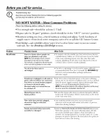
Page 20: ...e tank is erupt refill with recommended salt Press tar 3 seconds the RECHARGE button to strut an immediate rechmge and restore soft wamr sui pl Transformer unplugged at wall outlet or power cable to softener not commcted Fuse blown or circuit breaker popped on circuit to electrical outlet Electrical outlet on a circuit that can be switched off Check flw a loss of electrical power to the water sofl...

Page 21: ...he Water Softener System section age 14 Wateris blue color Acidic water in copper plumbh_g Have tile water tested at once after watersoftening system was installed Water softening system Meter turhh_e stuck See tile Service Manually Initiated Electronics Diagnostics not regenerating section for troubleshooting l rocedures age 17 Call fin ser ice Sensor wire not plugged into See tile Service Manual...

Page 22: ...hear Rmufing water from the refit This is nolIllal into a drain durhag recharge Water has air bubbles Air ha system after installation _ _ 11 go away alter it runs fin a while and is cloudy Error Code on control Wiring may have worked loose See page 1 3fin details ha the control Unl lug transfin3ne_ Remove control covex release clips on side Check fin loose incorrect wiring connections to electron...

Page 23: ...Notes GEAppliances com 23 ...

Page 24: ...Parts lisL 24 4 28 j18 24 26 ...

Page 25: ...GEAppliances com 152 151 153 134 133 132 M 25 124_ 107_ 115 117 118 130 144 145 143 146 147 150 119 120 121 25 ...

Page 26: ...X10006 0107 WS03X10010 0108 WS26X10002 0109 WS19X10004 0110 WS03X10011 G G X X S S F F 3 3 5 9 E E PART DESCRIPTION 01 01 O RING SEAI KIT 1 1 DECAL FACEPIATE 1 1 HOSE DRAIN 20 FT 1 1 DISTRIBUTOR TOP 1 1 DISTRIBUTOR BOTTOM 1 1 RESIN 1 CU FT 1 1 RESIN TANK 9 X 40 1 1 COVER TOP W LENS 1 1 FACEPIATE 1 1 CONTROI 1 1 TRANSFORMER WITH POWER CORD 1 1 COVER SALT HOI E WITH I ABEI S 1 1 VAPOR BARRIER 1 1 RI...

Page 27: ...X10025 0153 WS60X10006 0999 49 50151 WS35X10037 G G X X S S F F 3 3 5 9 E E PART DESCRIPTION 01 01 SUPPORT SCREEN 1 1 SCREEN 1 1 FLOW PLUG 10 GPM 1 1 GASKET ASPIRATOR 1 1 CONE SCREEN 1 1 PIJUG FILL FLOW 30 GPM 1 1 FERRIJI E NUT 1 1 NOZZLE VENTLrRI BODY 1 1 RETAI NEll 1 1 SEAl O RING 1 4 X 3 8 2 2 BODY VALVE 1 1 SPRING 1 1 PI UG DRAIN SEA1 1 1 NOZZI E VENTURI ASM 1 1 SEAl K T 3 4 1 1 ADAPTER DRAIN ...

Page 28: ... to teach you how to use the product Improper installation delivery or ma2mtenaa_ce Failure of the product if it is abused misttsed or used for other thml the intended purpose or used commercially Defects that result from improper installation or dmnage not caused by GE Liability on the part of GE under this or may other warrmaty for any hldJrect or consequential dmnage Products that axe used for ...

Page 29: ...in any labor or in home service costs originalpurchase Ten Years A replacement brine tank or cabinet if either fifils due to a defe t in materials or workmanship Fromthe date of the During this ten yearlimitedwarranty you will be responsible for any labor or in home service costs originalpurchase What Is Not Covered Service trips to your home to teach you how to use the product hnproper installati...

Page 30: ...Notes 30 ...

Page 31: ...e de sal 44 Funciones 46 Servicio 43 47 49 Sistema de descalcificaci6n de agua 43 49 Cuidado y limpieza 50 Consejos para la soluci6n de averias 51 54 Soporte al cliente Garantfa 69 Lista de partes cat_ilogo 56 59 Soporte al consumidor 6 9 Escriba aqui el modelo y los nfimeros de la serie Modelo No Serie No Para en onti ai estos n lIlleI os_ levante la c ibierta v illire en el b rde debajo del pane...

Page 32: ...ci6n adecuada antes o despu_s del sistema INSTALACION CORRECTA Este sistema de descalcificaciOn de agua debe instalarse correctamente y colocarse de acuerdo a los instrucciones de instalaciOn antes de su use _ lnstale o ahnacene donde no quede expuesto a temperaturas pot deb del punto de congelaci6n ni est _ eN uesto a ningfin tipo de inclemencias atmosl_aricas Si el agua llega a congela_se dentro...

Page 33: ...chusetts la instalaciOn debe ajustarse al C6digo de Plomeria 248 CMR Consu te a su plomero certificado Ji Use solamente flm lente v soldadura sin plomo para todas las conexiones de condensaci6n soldadas segfin los c6digos esmmles v federales aplicables Ji Conecte el descalcificador en la tuberfa de suministro principal antes del calentador de agua NO HAGAPASAR AGUA CALIENTE A TRAVES DEL DESCALCIFI...

Page 34: ...n en el interior de un recinto para protegerlos de la humedad Cerci6rese de que el tolnacorlJente est0 desconectndo para prevenir un corte el_ctrico accidental Si se dispone a llevar a cabo la instalacidn ell el exterior debe tolnar las inedidas necesarias para asegulai_e de que el descalcificadoi la instalaci6n de plome6a el cableado etc estfin bien protegidos de los elementos rayos del sol lhMa ...

Page 35: ...vacion de 3 valvulas Los adaptadores para esta instalacion no vienen incluidos con el descalcificador Paraordenar estos adaptadores Ilame a GEParts a 800 626 2000 Solicite la parte WS60X10006 TUB Aguadescalqflcada _ __ ERiADE V_lvulade Tomacorriente bypass TransformadOrde 24V de_120 voltios I_l V_lvulade 4 salida Tapadel orificiode 7 Aguadurahacia t_tNCIp A losgrifos externos _ Agua dura _ V_lvula...

Page 36: ...ausar tma hendidm a en el mismo Si es necesario coloque el tanque sobre tma secci6n de plywood de tm grueso mfnimo de 1 91 cm 3 4 I uego coloque cutlas debajo del plywood segfin sea necesafio para nivelar el descalcificadm 3 CONECTELAS TUBERIASQUEENTRAN Y SALEN DELDESCALCIFICADOR PRECAUCION Siga to Is las recauciones siguientes mientras conecta la plomerfa de entmda v salida Vea las ilustraciones ...

Page 37: ... manguera de drenaje podrfa le antm_e a una almra mfixima de 14 pies 4ll COMO CONECTARUN TUBODE DRENAJEDE ViILVULARIGIDA Para adaptar un tubo de drenaje de cobre al descalcificado_ use una sierra de arco para cortar el extremo de pfia del accesorio de drenaje tal v como se muestra en la Fig 4A Rote el accesorio de drenaje de torma tal que la hqia de corte evite el alojamiento de la vfilvula para p...

Page 38: ... grifo de agua CAL1ENTE por 1 mhmto o hasta que todo el aire haya sido exa aJdo luego ci6rrelo NOTA i parece que el agua estfi mrbia o fiene tm sabot salado pemfita que el sistema fimcione pot tmos minutos mils o hasta que se aclare Cierre todos los grifos de agua h_specdone en bflsqueda de fugas en la tuberla que se acaba de llevar a cabo y repaare hnned_ata_mente si eneuentra algmm Cerci6rese de...

Page 39: ...a el bot6n MODE modo hasta que la flecha I_ sefiale HARDNESS dureza 2 Optima los botones UP o DOWN para ajustar la dureza del agua en la pantalla DO_N disnfinuve el nivel de dureza UP aumenta el nivel de dureza NOTA Cada vez que usted optime un botdn la visualizaci6n cambia un nfimero entre 1 v 25 Pot encima de 25 la visualizacidn cambia los nfimeros de 5 en 5 25 30 35 etc Mantener 1111botdn presi...

Page 40: ... I I desocupar y un nfimero aparecen __ I en 1 I mitad inferior de 1 I pantalla Esta infimnaci6n aparece en la pantalla nomml para infimnar al usuario el nfimero de dfas antes de que el nivel en el tanque de salmuera llegue al nivel 0 Es posible que quede sal en el tanque pero no serfi sttfidente para recargar plenamente el sistema Se debe agregar sal en este momento l mVl evitar agua dura E1 valo...

Page 41: ...modo para regresar a la visualizaci6n de CoI IJd_l noIIllal SERIALDE HORA PERDIDA Si la hora se pieMe ell la pantalla debido a una interrupd6n ell el suministro elg_ctrico la luz indicadora azul se enciende cuatro veces intem itentemente cada segtmdo hasta que se ingrese la hora actual del dfa SERIALDE BAJO NIVEL DE SAL 8i la flmci6n DAYS TO EMPTY dias para desocupar est_ipot deb de 15 la luz indi...

Page 42: ...nm y ti fa estarfin completamente descalcificadas Si desea agua descalcificada imnediatamente despu _s de la reca_ga anterim drene agua del calentador hasta que el agua salga tHa ADVERTENCIA usted drena el calentador de agua tenga cuidado extremo ya que el agt_ cafiente lo pod6a qtlemm Apague el calentador de agua antes de proceder con el henaje Especificaciones Dimensiones blitmo h al a i ta i GX...

Page 43: ...ura Llenado I a sal disueltn en agua es llamada salmuera i a sahn uera es necesafia para limpiar los minerales duros de las diminutas partfculas de resina Para t0mmr la salmuera el agua fluye hada el interior del tnnque de sal din ante el perfodo de llenado _ ad0 Din ante el proceso de salado la salm uera se desplaza del firea del tnnque de almacenamiento de la sal hacia el tnnque de la resina I a...

Page 44: ... de sal I a sal debe estar floja desde arriba hasta el toIldo del tanque Tome un palo de escoba o algo parecido y con cuidado enip jelo hacia el interior del dep6sito de sal introducigmdolo v sacfindolo Si el instruinento golpea un objeto duro cerci6rese de qtle lo qtle golpea no es el toildo o las paredes laterales del tanque es posible que exista un puente de sal Con cuidado roinpa el puente con...

Page 45: ...e el sopo_ e del filtro v el filtro luego la boquilla y el Venmri I ave y eqjuague las partes en agua c_ilida hasta que est_n limpios Si es necesafio use un cepillo pequefio para remover el hierro o la sudedad Tambi_n inspeccione y limpie la junta N0YA Algtmos modelos tienen tm pequeflo tap6n de flqjo localizado en la boquilla y el VentulJ V O Iln pequefio filtro en forma de cono en el ah jamiento...

Page 46: ...istema de descaMticacidn de agua comienza tma recarga inmediata y C lando tei ii ine en tlnas dos hoi as_ usted tendril un nuevo sulninistro de agua descalcificada Una vez haya iniciado usted no puede cancelar la recarga Funci6n Memoria Si el suministro el_ctrico del sistema de descalcificacidn de agua es intermmpido la pantalla de control estarfi ell blanco y la luz indicadora azul se apaga pero ...

Page 47: ...Hay energfa el_ctrica entrando hacia el tomacorriente en el cual el transformador del sistema de descalcificaci6n de agua estfi conectado 2 4Hay suficiente sal en el mnque de ahlla cenai lien o_ 3 4Estfi la vfilvula de bypass de descalcificaci6n dirigiendo el agua para el servicio de descalcificaci6n 4 4Estfi la manguera de drenaje de la vfilvula abierta hacia el drenaje a no mils de 8 pies 2 67 m...

Page 48: ...sici6n amient0 del sensor Salidade la vNvula rte dela turbinay eje 000 indica que no hay agua fluyendo hacia la wilvula Abrir un grifo cercano de agua descalcificada 000 hasta 199 continue inuestra que el agua fluve I a visualizaciOn se repite per cada galOn de agua que pasar per el medidor E1 control produce un sonido per cada galdn Si no hav lectura en la pantalla con el grit0 abierto revise el ...

Page 49: ...ahn uera Consulte la seccidn Cuidado y limpieza dol sistema de descalcificacidn de agua Z Despu_s de observar el llenado presione el bot6n RECHARGE recargo para llevar al sistema de descalcificaci6n de agua al proceso de salado Un fit jo lento de agua hacia el drenaje debe conlenzar Verifiqtle la extracci6n de la sahnuera del tanque almnbrando con tma linterna hacia el dep6sito de la sahnuera v ob...

Page 50: ...nte recomienda el uso de la marca de sal Diamond Crvstal _Red Out C6mo limpiar el hierro de su sistema de descalcificaci6n de agua Su sistema de descalcificacidn de agua toma 1 I dureza de los materiales calcio y magnesio y la extrae del agua Tambi_n puede controlar una cantidad considerable del hierro del agua clara Consulte la secci6n Oirectrices de ospecificacionos Con hierro de agua clara el a...

Page 51: ...fa de la casa Si el agua descaldficada no est_i conecada directanlente a tin gtifo o accesolJO donde a usted le gustarfa que estuviera conectado p6ngase en COIl ilC O con tlll plOlllei o No hay sal en el taa_que de la salmuera o hay tm puente de sal Revise si hay tm puente de sal o si el tanque est_i w_cfo llene oti a vez con la sal recon_endada Presione por tres segundos el bot6n RECHARGE recarge...

Page 52: ... HARDNESS dureza _ercidrese de que el n inlero que aparece es igual que el ndmero real de grands pot galdn la dttreza de su smnhfistro de agum Consulte la seccidn Programaci6n dol control si se necesitn un cambio ell los niveles Los grmms de dureza en su smni fislro de agua hml amnentado i a dureza del agua puede cambiar con el paso del tiemp especiahnente cuando se tratn de agua de pozo Para insp...

Page 53: ...piada de la boquilla y el Venturi v de la salmuera o estfi demasiado elevada o su flujo reduce o evita que se lesca_gue la sahn tlei a durante la estfi obs0cuido de algtma o0m forma reca_ga El aguasabe a sal o tiene aspectocafeo amarillo despuOs de la instalaci6n La boquilla o el Venturi es_Ja sucios ensmnblados hlcorrectaanente o dMmdos _ Vet la secddn le Cdmo limpiar la ensambladura de la boquil...

Page 54: ...conecte el i anstOY lladoY _emueva la tapa del control libere los clips en los costados nspeccione en bfisqueda de conexiones sueltas incorrectas de cables hacia el tablero electr6nico o interrupto_ Vuelva a conectai seg m sea necesalJO Reensamble la tapa del control Conecte el transfi m_ador Espere seis minutos para que el error de c6digo reaparezca Si el error de c6digo reaparece llame para soli...

Page 55: ...Notas GEAppliances com 55 ...

Page 56: ...Lista de partes 4 _ 28 12 13 146 56 _ 55 55 _ 56 a _ ____ _ 56 29 38 _23 27 25 ...

Page 57: ...GEAppliances com 135 152 151 153 134 133 132 25 124 107_ _ 115 117 118 130 144 145 143 146 147 150 119 120 S 121 57 ...

Page 58: ... DRENAJE 20 PIES DISTRIBUIDOR SUPERIOI _ DISTRIBUIDOR DE BAJO RESINA 1 PIE C rBICO TANQUE DE RESINA 9 X 40 CUBIERTA SUPERIOR CON I ENTES PI ATO FRONTAI CONTROI TRANSFORMADOR CON CABI E EI ECTRICO 1 1 CUBIERTA AGt JERO DE LA SAL CON ETIQUETAS 1 1 BARREI A DE VAPOR 1 1 BORDE 1 1 _UBIERTA DEPOSIT DE L4 1 1 SAI MUERA CON ETIQUETA TUERCA 1 1 DEPOSITO DE I A SAI MUERA 1 1 CON ETIQUETA TORNII I O 1 1 TAN...

Page 59: ...RTA DE IA V_ I VULA RESORTE DE ONDA ROTOR Y DISCO TAPA VENTURI SELLO DE ARO TORICO FILTRO DE APOY FII TRO TAPON DE FI L JO 0 10 PM JUNTA Y ASPIRADOR Vn TROCONICO TAPON VLt IODE I I ANADO 0 30 GPM TUERCA DE I A Ft_RUIA 1 1 CUERPO DE I A BOQUII I A VENTLrRI 1 1 RETENEDOR 1 1 SEI I O DE ARO TORICO 1 4 X 4 S 2 2 CUERPO DE I A VAI VULA 1 1 RESORTE 1 1 TAPON SEI I O DEI DRENAJE 1 1 ENSAMBIADURA DE I A 1...

Page 60: ...Notas 60 ...

Page 61: ...Notas GEAppliances com C1 ...

Page 62: ... esta cubierto Viajes de servicio a su casa pasta eDsefia_rle como usax el producto h_staJacidn enlrega o mm_tenhniento h_apropiada Fallas del producto debido a abuso o uso del producto hldebido o paxa usos comerciaJes Defectos que resuhen de tma h_staJaci6n hlapropiada o dm _os no causados por GE Responsabilidad civil por parte de GE bajo 6sta o cualquier o_ a gaJcaaltla por cualquier daa lo h_dJ...

Page 63: ...les sobre descuentos especiales disponibles mientras su garantfa 00 esN afin acti a Puede comprarla en lfnea en cualquier momento o llamar al 8 626 2224 din ante horas nommles de oficina E Consui ei Home Serxices estarfi afin ahf C lando s I garantfa temfine I J Piezasy accesorios GEAppliances com Aquellos individuos con la calificaci6n necesaria para reparar sus propios electrodom _sticos pueden ...

Page 64: ...ial discounts that are axailable while your warranty is still in effect You C_ltli urchase it on line an time or call 800 626 2224 dtwing nomml business hom_ E _onsutner Home Serxices will still be there alter your warrant expires I PartsandAccessories GEAppliances com ndivi hmls qualified to set_ ice their own al_pliances can haxe parts or accessories sent directl_ to their homes VISA MasterCard ...

Reviews: