background image

Installation Instructions.

Installing the Tubing

1.

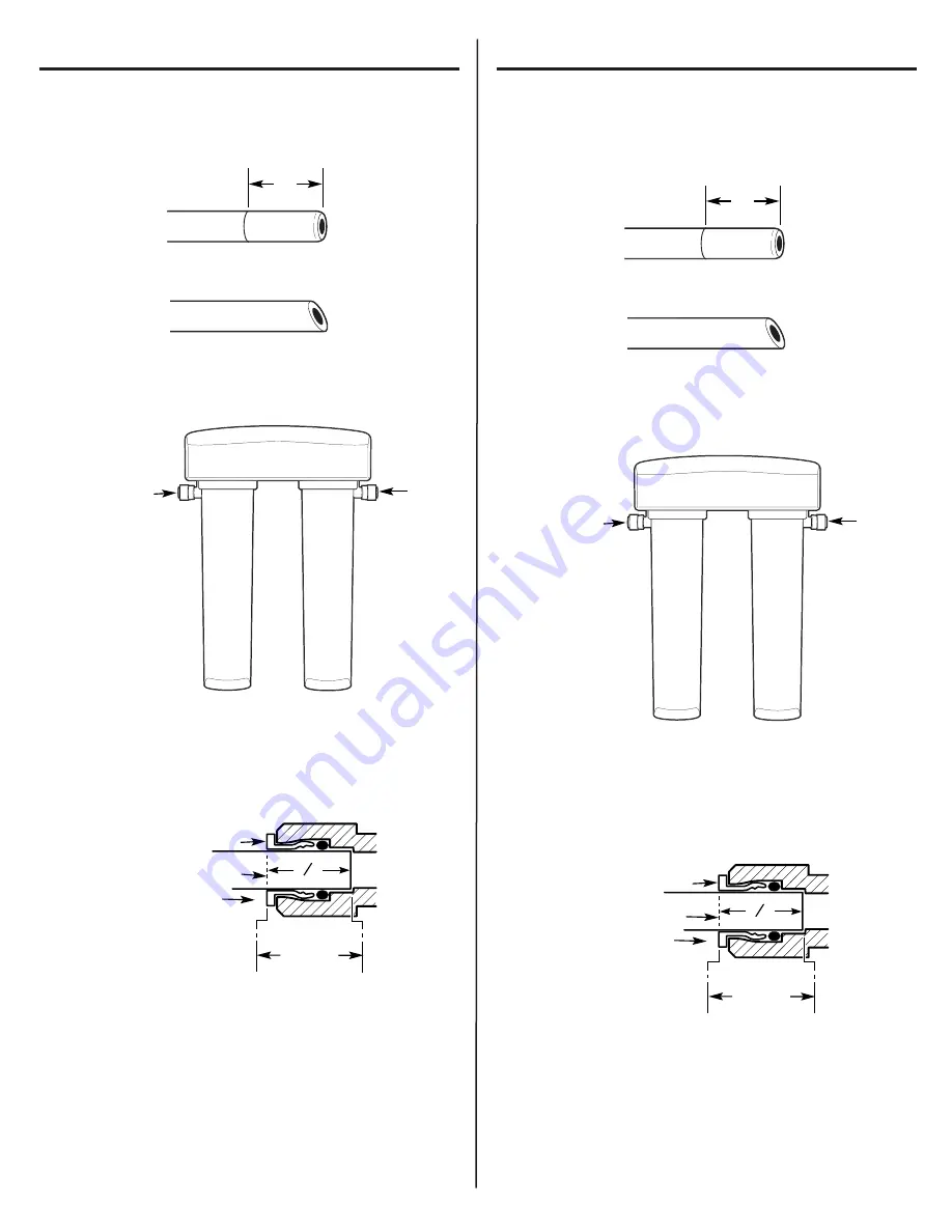
Measure 3/4

from the end of each remaining piece of tubing (faucet

end and inlet end) and mark with a pencil (Fig. 8). (Check for roundness,
smoothness, cuts, nicks, flat spots and sharp edges.)

2. NOTE: Water flow is from left to right. Water inlet is on the left side

and water outlet is on the right side. Failure to follow will result in
water leaks when filter canisters are removed. 

3

Push the tubing firmly into each fitting on the manifold until the line is
flush with the fitting collar. (If the tubing is removed, re-cut the end,
measure, mark and re-insert). Tubing must be fully inserted to avoid
leaks (Fig. 9). 

(To remove tubing, depress and hold white collet; pull

tubing out to remove.)

4

Pull out slightly on tubing to ensure a good seal.

5.

Install the other end of the tubing from the inlet side of the manifold to
the feed water adapter.

NOTE:

Inspect the ends of the tubing to be sure there are no

imperfections and that the end of the tubing is cut square. It may be
necessary to cut the tubing again.

Instrucciones de instalación.

Cómo instalar la tubería

1.

Mida una distancia de 3/4 pulgada desde el extremo de cada pieza
restante de tubería (extremo del grifo y extremo de la entrada) y marque
con lápiz (Fig. 8). (Revise que quede pareja, lisa y que no tenga cortes,
hendiduras, puntos planos o bordes filosos).

2. NOTA: El flujo de agua es de izquierda a derecha. La entrada del agua

está en el lado izquierdo y la salida en el lado derecho. No seguir
estas instrucciones podría resultar en fugas cuando los cartuchos de
los filtros sean removidos.

3

Empuje la tubería firmemente hacia cada conexión en el recolector
hasta que la tubería esté nivelado con el collar. (Si se retira la tubería,
vuelva a cortar el extremo, mida, marque y vuelva a insertar). La tubería
debe estar firmemente insertada para evitar fugas (Fig. 9). 

(Para retirar

la tubería: Libere y sostenga la boquilla blanca; hale la tubería hacia
fuera para retirar.)

4

Saque la tubería ligeramente para asegurar un buen sellamiento.

5.

Instale el otro extremo de la tubería desde el lado de la entrada del
recolector al adaptador de suministro de agua.

NOTA:

Inspeccione los extremos del tubo para asegurarse que no

haya imperfecciones y que el extremo de la tubería se haya cortado
perpendicularmente. Es posible que se necesite volver a cortar 
la tubería.

3/4

(19 mm)

Fig. 8

INCORRECT

Inlet from supply valve

Outlet 
to faucet

3/4

(19 mm)

Fig. 8

INCORRECTO

3

4

"

Engagement

3/4

(3/8

tubing) 

White Collet 
(DO NOT REMOVE)

Insertion line

Insert tubing

Fig. 9

Entrada de la válvula
de suministro

Salida hacia
el grifo

3

4

"

Enganche

3/4

(tubería de 3/8

)

Boquilla blanca 
(NO RETIRAR)

Línea de inserción

Insertar tubería

Fig. 9

13

Summary of Contents for GXSL55F

Page 1: ...tional against NSF ANSI Standard 42 for the reduction of Chlorine Taste and Odor and Particulate Class I and Standard 53 for the reduction of Lead Cyst Turbidity Asbestos Mercury Lindane Atrazine Toxa...

Page 2: ...AD IMPORTANTE LEA TODAS LAS INSTRUCCIONES ANTES DE USAR ADVERTENCIA Para su seguridad se deber seguir la informaci n de este manual para minimizar el riesgo de da os a la propiedad o lesiones personal...

Page 3: ...Sheet for details Pautas de las especificaciones Se pueden reducir muchos malos olores y o sabores del agua usando cartuchos de carbono para el filtro Se usan principalmente para reducir el olor y sa...

Page 4: ...forma a las normas 42 y 53 NSF ANSI en cuanto a las afirmaciones espec ficas de desempe o seg n verificaci n y admisi n de los datos de las pruebas Consulte la hoja de datos del desempe o para detalle...

Page 5: ...rameter MCL Challenge Concentration Average Average Maximum Average Minimum Reduction USEPA Calidad del Promedio Effluyente de reducci n Reducci n Par metro MCL influyente concentraci n influyente Pro...

Page 6: ...relativos a la salud Turbidity Turbidez 1 NTU 11 1 NTU 11 08 NTU 0 21 NTU 0 38 NTU 98 04 96 20 0 5 NTU Cysts Quistes 99 95 red Min 50000L 141750 L 1 L 2 L 99 99 99 99 99 95 Asbestos Amianto 99 red 107...

Page 7: ...je de la reducci n qu mica y el nivel m ximo del agua del producto calculado a un punto de ruptura de 95 de cloroformo seg n lo determinado en la prueba de calificaci n sustituta 6 The surrogate test...

Page 8: ...ber a flexible del grifo En la ilustraci n que aparece a continuaci n se muestra una conexi n t pica usando el accesorio para el suministro de agua incluido 1 Cierre la v lvula de agua que se encuentr...

Page 9: ...r conectarse con el tubo de 1 4 de pulgada suministrado con el sistema No se suministra con el producto consulte en la ferreter a local o tienda de servicios para el hogar La v lvula de asiento t pica...

Page 10: ...ada por bater a Seleccione uno de los siguientes lugares para instalar el grifo 1 En un orificio accesorio rociador existente en el lavaplatos u orificio de dispensador de jab n 2 En un orificio a per...

Page 11: ...base de los cartuchos de los filtros y el piso o la base del gabinete cualquier espacio inferior presentar dificultades para retirar los cartuchos de los filtros Fig 5 Permita suficiente espacio para...

Page 12: ...ntil a desired fit is achieved Instrucciones de instalaci n Montaje del sistema Montaje del sistema a los tornillos instalados en la pared 1 Remueva la envoltura de pliegue del sistema del filtro 2 Cu...

Page 13: ...z Fig 8 Revise que quede pareja lisa y que no tenga cortes hendiduras puntos planos o bordes filosos 2 NOTA El flujo de agua es de izquierda a derecha La entrada del agua est en el lado izquierdo y la...

Page 14: ...i n de la bater a 1 Use un destornillador de pala plana peque o o una moneda para retirar la bandeja de la bater a A en el costado de la base del grifo 2 Instale una bater a CR2032 de 3 voltios B con...

Page 15: ...leaks around the system 5 Once water starts to flow out of the faucet allow the system to run for 5 minutes to flush out any harmless carbon fines that may be present 6 Turn off faucet and check arou...

Page 16: ...link rapidly 5 times to indicate proper installation and operation Indicator light on the Battery may need to be Observe orientation markings on the holder and install correctly faucet base is not rep...

Page 17: ...5 veces para indicar la instalaci n y operaci n correcta La luz indicadora La bater a podr a necesitar Observe las marcas de orientaci n en el recept culo e instale en la base del grifo reemplazo o po...

Page 18: ...Notes Notas 18...

Page 19: ...usted prefiera El registrar su producto a tiempo le proporcionar si surgiera la necesidad una mejor comunicaci n y un servicio m s r pido bajo los t rminos de su garant a Tambi n puede enviar su tarje...

Page 20: ...n will allow for enhanced communication and prompt service under the terms of your warranty should the need arise You may also mail in the preprinted registration card included in the packing material...

Reviews: