GE M
EDICAL
S
YSTEMS
D
IRECTION
2392751-100, R
EVISION
3
V
IVID
™ 4 S
ERVICE
M
ANUAL
8-80
Section 8-5 - Back End Parts Replacement
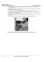
4.) Re-connect the mains power cable [
B
] to the motherboard (beside the ECG location).
5.) Re-connect the mains power cable (4-pin flat connector [
C
] - Part No. 2252981) to the rear of the
BEP, and fasten with cable ties.
6.) Re-connect the power cable to the Floppy Disk (labelled [
D
] in
); refer also to
7.) Slide the PC-VIC & hard disk out sufficiently to be able to re-connect the power cable (labelled [
E
]
in
) to the PC-VIC; refer also to
8.) Re-connect the data cable to the PC-VIC (see
9.) Re-connect the power cable to the Hard Disk (labelled [
F
] in
10.)Return the Ground cable and screw that fastens the PC-VIC in position, as shown in
11.)Re-connect the power cables to the media drives (and CD-RW [
G
]) and MOD [
H
] .
12.)Carefully place the ECG Module in the front of the BEP, sliding it into position and re-connecting
the power cable [
I
] to the rear of the ECG Module. (Refer to the
BEP2 - ECG Module Installation
13.)Gently slide the power supply up into the final position in the BEP casing.
14.)Check that all cable connections are secured firmly and fasten with additional cable ties, as
necessary.
NOTE:
Make sure that all data cables, memory boards, etc. are securely in position and that nothing has
erroneously become disconnected during the power supply removal procedure.
15.)Stand the BEP2 upright.
16.)At the rear of the BEP2, return and loosely tighten the four screws that fasten the power supply in
position on the BEP, as shown in
17.)Return the BEP front cover as described in the
BEP2 - Front Cover Installation Procedure
18.)Return the one screw previously removed from the top of the side cover, as shown in
19.)Fully tighten the four screws at the rear of the BEP (refer to
) to secure the power supply
firmly in position.
20.)Return the BEP2 side covers, as described in the
BEP2 - Side Cover Installation Procedure
21) Carefully return the BEP2 to the original position on the machine chassis, and proceed as follows:
a.) Re-connect all the cables on the rear of the BEP (refer to the step-by-step instructions provided
Back End Processor Installation Procedure
b.) Return the screws of the
lower
left and
right
BEP brackets see
a.) Return the two screws of
upper
BEP bracket (
).
22.)Replace the Vivid™ 4 rear cover - refer to the
Rear Cover Installation Procedure
23) Remove the Vivid™ 4 left and right side covers - refer to the
Side Covers Installation Procedure
24) Re-connect the mains AC power cable for the mains power wall outlet.
25) Turn ON the main circuit breaker located on rear of the Vivid™ 4.
26) Turn ON the Vivid™ 4 by pressing the ON/OFF button on the Control Console.


