GE M
EDICAL
S
YSTEMS
D
IRECTION
2392751-100, R
EVISION
3
V
IVID
™ 4 S
ERVICE
M
ANUAL
8-110
Section 8-6 - Lower Section Components Replacement
8-6-9-5
Front Wheel Installation - Procedure 1
Note:
The machine will remain stable, even after one wheel has been removed. However, for a safer
working environment, it is recommended to support the unit with wooden blocks or a jack.
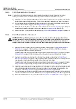
1) Install the new wheel (Part No. 2269437) on the machine chassis in the same position as that of the
previously-removed wheel. Make sure it is correctly positioned, parallel to the other front wheel.
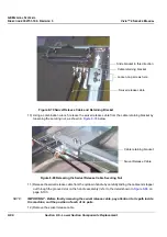
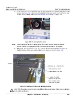
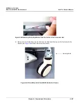
2.) Lift the transverse arm (wheel position bar) and secure it into position by re-attaching the spring
washer to the central locking pin (refer to
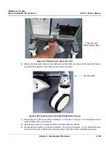
3.) Return the four bolts (three wrench bolts and one Allen bolt - removed in
on page 8-107) and
make sure that wheel is secured firmly to the chassis (see
4.) Return the Vivid™ 4 front cover, as described in the
Front Cover Installation Procedure
8-6-9-6
Front Wheel Installation - Procedure 2
WARNING: When performing this procedure, the machine must be safely supported on two
wooden blocks (or on a jack capable of supporting the weight of the machine). Do not lean on
the machine, or leave it unattended without support, when the wheels have been removed.
Always remove and replace one wheel at a time, before attempting to remove the second wheel.
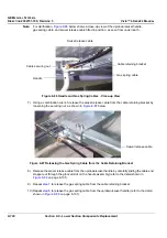
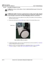
1) Having removed one wheel from the machine chassis (as described in
on page 8 - 108), install one of the new wheels (Part No. 2392789) in its place,
ensuring that the wheel is correctly positioned.
Install the four bolts (three wrench bolts and one Allen bolt removed in
to
on page 8-109]), making sure that the wheel is secured firmly to the chassis.
2) Having removed the second wheel from the machine chassis (as described in
on page 8 - 108), install the other new wheel in its place, ensuring that the
new wheel is correctly positioned, parallel to the other new front wheel.
Install the four bolts (three wrench bolts and one Allen bolt removed in
to
on page 8-109]), making sure that each wheel is secured firmly to the chassis.
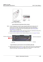
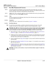
3.) Install the new transverse arm (wheel position bar) by hooking it onto the central locking pin located
above the brake pedal and securing it into position (attach the spring washer [supplied] to the
central pin - refer to
4.) Lift the transverse arm
upwards
and attach a new locking spring washer (supplied) to the underside
of each end of the transverse arm. Refer to
5.) Return the Vivid™ 4 front cover, as described in the

