background image

i-14      

LOGIQ V3/V5/V5 Expert – Basic Service Manual

5726264-100 English Rev.8

Service Safety Considerations

For a complete review of all safety requirements, refer to 
Chapter 1 in the Service Manual.
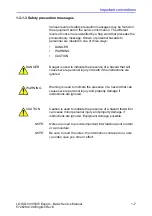
DANGER

DANGEROUS VOLTAGES, CAPABLE OF CAUSING DEATH, 
ARE PRESENT IN THIS EQUIPMENT. USE EXTREME 
CAUTION WHEN HANDLING, TESTING AND ADJUSTING.

WARNING

Use all Personal Protection Equipment (PPE) such as gloves, 
safety shoes, safety glasses, and kneeling pad, to reduce the 
risk of injury. 

Summary of Contents for H48612AA

Page 1: ...GE Technical Publication LOGIQ V3 V5 V5 Expert Basic Service Manual Direction Number 5726264 100 English Rev 8 All Material Copyright 2016 2017 by General Electric Company Inc All Rights Reserved ...

Page 2: ...sound system Copyright 2016 2017 General Electric Company GE Medical Systems a General Electric Company going to market as GE Manufacturer GE Medical Systems China Co Ltd No 19 Changjiang Road WuXi National Hi Tech Development Zone Jiangsu P R China 214028 TEL 86 510 85225888 FAX 86 510 85226688 www gehealthcare com ...

Page 3: ...327 or 1 262 524 5698 Revision Date YYYY MM DD Reason for change Rev 1 2016 01 21 Initial Release Rev 2 2016 06 12 Update control panel figure and book format Rev 3 2016 08 10 Update warning label Rev 4 2016 08 24 Update peripheral list Rev 5 2016 10 12 Update unpacking process Rev 6 2017 04 19 Update as software updates Rev 7 2017 06 14 Add manufacturer information Rev 8 2017 08 23 Update periphe...

Page 4: ...i 2 LOGIQ V3 V5 V5 Expert Basic Service Manual 5726264 100 English Rev 8 Important precautions Translation policy ...

Page 5: ...LOGIQ V3 V5 V5 Expert Basic Service Manual i 3 5726264 100 English Rev 8 ...

Page 6: ...i 4 LOGIQ V3 V5 V5 Expert Basic Service Manual 5726264 100 English Rev 8 ...

Page 7: ...LOGIQ V3 V5 V5 Expert Basic Service Manual i 5 5726264 100 English Rev 8 ...

Page 8: ...i 6 LOGIQ V3 V5 V5 Expert Basic Service Manual 5726264 100 English Rev 8 ...

Page 9: ...LOGIQ V3 V5 V5 Expert Basic Service Manual i 7 5726264 100 English Rev 8 ...

Page 10: ...i 8 LOGIQ V3 V5 V5 Expert Basic Service Manual 5726264 100 English Rev 8 ...

Page 11: ...LOGIQ V3 V5 V5 Expert Basic Service Manual i 9 5726264 100 English Rev 8 ...

Page 12: ...i 10 LOGIQ V3 V5 V5 Expert Basic Service Manual 5726264 100 English Rev 8 ...

Page 13: ...LOGIQ V3 V5 V5 Expert Basic Service Manual i 11 5726264 100 English Rev 8 ...

Page 14: ... within this 14 day period Certified electrical contractor statement For USA Only All electrical Installations that are preliminary to positioning of the equipment at the site prepared for the equipment shall be performed by licensed electrical contractors Other connections between pieces of electrical equipment calibrations and testing shall be performed by qualified GE personnel In performing al...

Page 15: ...n listing the system type manual title part number revision number page number and suggestion details Mail the information to GE Medical Systems China Co Ltd No 19 Changiang Road Wuxi National Hi Tech Dev Zone Jiangsu P R China 214028 TEL 86 510 85225888 FAX 86 510 85226688 GE employees should use TrackWise to report service documentation issues These issues will then be in the internal problem re...

Page 16: ...afety requirements refer to Chapter 1 in the Service Manual DANGER DANGEROUS VOLTAGES CAPABLE OF CAUSING DEATH ARE PRESENT IN THIS EQUIPMENT USE EXTREME CAUTION WHEN HANDLING TESTING AND ADJUSTING WARNING Use all Personal Protection Equipment PPE such as gloves safety shoes safety glasses and kneeling pad to reduce the risk of injury ...

Page 17: ...asic service software does not extend to or cover this software or related documentation If you are a GE employee or a customer who has entered into such a license agreement with GE to use this proprietary software you are authorized to use this Material according to the conditions stated in your license agreement However you do not have the permission of GE to alter decompose or reverse assemble ...

Page 18: ...i 16 LOGIQ V3 V5 V5 Expert Basic Service Manual 5726264 100 English Rev 8 ...

Page 19: ...ical users of the Proprietary Service Manual 1 4 Purpose of Operator Manual s 1 4 LOGIQ V3 V5 V5 Expert models covered by this manual 1 5 Important conventions Conventions used in book 1 6 Standard hazard icons 1 8 Product icons Labels locations Rating Plate Location 1 11 Safety considerations Contents in this section 1 16 Introduction 1 16 Human Safety 1 16 Mechanical safety 1 19 Electrical safet...

Page 20: ...2 15 Minimal floor plan suggestion 2 16 Recommended floor plan suggestion 2 17 Networking setup requirements 2 18 Chapter 3 System Setup Overview Contents in this chapter 3 2 Setup reminders Average setup time 3 3 Setup warnings 3 3 Receiving and unpacking the equipment Purpose of this section 3 6 Contents in this section 3 6 Warnings for receiving and unpacking 3 6 LOGIQ V3 V5 V5 Expert transport...

Page 21: ... of this chapter 4 2 Contents in this chapter 4 2 Special Equipment required 4 2 General procedures Overview 4 4 Power ON Boot Up 4 5 Power off 4 8 Check System Date and Time 4 10 Manufacturer 4 11 Removable media 4 11 Backup and Restore Database Preset Configurations and Images 4 12 Functional checks Overview 4 21 Contents in this Section 4 21 Preparation 4 21 Basic Controls 4 22 Control Panel 4 ...

Page 22: ... Mechanical Functions Checks 4 43 Application Turnover Check List Software Configuration Checks 4 45 Site Log My Trainer Overview 4 47 Chapter 5 Components and Functions Theory Overview Contents in this chapter 5 2 Block Diagram and Theory Block Diagram 5 3 Common Service Platform Introduction 5 5 Chapter 6 Service Adjustments Overview Contents in this chapter 6 2 LCD Monitor Adjustments Purpose o...

Page 23: ...ations 8 6 Recording important settings and parameters 8 7 Loading the System Software 8 8 Rewrite the Serial Number 8 22 Chapter 9 Renewal Parts Overview Contents in this chapter 9 2 List of Abbreviations Renewal Parts Lists Operator Console Assy 9 4 Probe 9 5 Peripheral 9 5 Power Cord 9 8 Manuals 9 9 Chapter 10 Care and Maintenance Overview Contents in this chapter 10 2 Warnings Why do maintenan...

Page 24: ...limits 10 21 Outlet test wiring arrangement 10 23 Grounding continuity 10 24 Chassis leakage current test 10 25 Probe leakage current test 10 27 When there s too much leakage current AC DC Fails 10 30 Chassis Fails 10 30 Probe Fails 10 31 Peripheral Fails 10 31 Still Fails 10 31 New Unit 10 31 ECG Fails 10 31 Inspection Paperwork Ultrasound Inspection Forms 10 32 Electrical Safety Tests Log Index ...

Page 25: ...4 100 English Rev 8 Chapter 1 Introduction This chapter describes important issues related to safely servicing the Ultrasound system The service provider must read and understand all the information presented here before installing or servicing the units ...

Page 26: ...w on page 1 3 1 3 Important conventions on page 1 6 1 4 Product icons on page 1 10 1 5 Labels locations on page 1 11 1 6 Safety considerations on page 1 16 1 7 Dangerous procedure warnings on page 1 24 1 8 Lockout Tagout LOTO requirements on page 1 25 1 9 Returning probes and repair parts on page 1 26 1 10 EMC EMI and ESD on page 1 27 1 11 Customer assistance on page 1 29 ...

Page 27: ...ns and Legal notes and the Table of Contents TOC An Index has been included after Chapter 10 Table 1 1 Contents in this manual Chapter number Chapter title Description 1 Introduction Contains a content summary and warnings 2 Site preparations Contains pre setup requirements for the LOGIQ V3 V5 V5 Expert 3 System Setup Contains setup procedure with procedure checklist for the system 4 General Proce...

Page 28: ...s not necessarily reflect the probes available on your ultrasound system Please refer to the probe list for available probes and features 7 Diagnostics Troubleshooting Provides procedures for running diagnostic or related routines for the LOGIQ V3 V5 V5 Expert 8 Replacement procedures Provides disassembly procedures and reassembly procedures for all changeable FRU 9 Renewal Parts Contains a comple...

Page 29: ... Expert models covered by this manual NOTE When not otherwise specified the contents of this manual applies to all LOGIQ V3 V5 V5 Expert models Table 1 2 LOGIQ V3 V5 V5 Expert Model Designations Model Number Description System SW H48612AA LOGIQ V3 R2 x x H48612AB LOGIQ V5 R2 x x H48612AC LOGIQ V5 EXPERT R2 x x ...

Page 30: ...e described next 1 3 1 1 Model designations This manual covers the LOGIQ V3 V5 V5 Expert Ultrasound systems listed in 1 2 4 LOGIQ V3 V5 V5 Expert models covered by this manual on page 1 5 1 3 1 2 Icons Pictures or icons are used wherever they will reinforce the printed message The icons labels and conventions used on the product and in the service information are described in this chapter ...

Page 31: ...otes are used to provide important information about an item or a procedure NOTE Be sure to read the notes the information contained in a note can often save you time or effort DANGER Danger is used to indicate the presence of a hazard that will cause severe personal injury or death if the instructions are ignored WARNING Warning is used to indicate the presence of a hazard that can cause severe p...

Page 32: ...gle or the symbols for Danger Warning or Caution as seen throughout this chapter In addition to text several different graphical icons symbols may be used to make you aware of specific types of hazards that could possibly cause harm NOTE Even if a symbol isn t used on the product or in this manual it may be included for your reference Table 1 3 Standard hazard icons ELECTRICAL MECHANICAL RADIATION...

Page 33: ...d Some others icons make you aware of specific procedures that should be followed Be sure to read the notes the information contained in a note can often save you time or effort Table 1 4 Standard Icons that indicates that a special procedure is to be used Avoid Static Electricity Tag and Lock Out Wear Eye Protection Hand Protection Foot Protection Wear Eye Protection ...

Page 34: ...V5 Expert Basic Service Manual 5726264 100 English Rev 8 1 4 Product icons It is important to refer to the current revision of the Ultrasound system s Basic User Manual for a full list of product labels prior to servicing the system ...

Page 35: ...sion of the Ultrasound system s Basic User Manual for a full list of product labels prior to servicing the system 1 5 1 Rating Plate Location LOGIQ V3 V5 V5 Expert labels are provided in English The labels are at the bottom of the system The label content may be different for different regions Please refer to the labels on the system for the actual content ...

Page 36: ...Introduction 1 12 LOGIQ V3 V5 V5 Expert Basic Service Manual 5726264 100 English Rev 8 1 5 1 Rating Plate Location continued Figure 1 1 LOGIQ V5 Expert Label Location ...

Page 37: ...Labels locations LOGIQ V3 V5 V5 Expert Basic Service Manual 1 13 5726264 100 English Rev 8 1 5 1 Rating Plate Location continued Figure 1 2 LOGIQ V5 Label Location ...

Page 38: ...Introduction 1 14 LOGIQ V3 V5 V5 Expert Basic Service Manual 5726264 100 English Rev 8 1 5 1 Rating Plate Location continued Figure 1 3 LOGIQ V3 Label Location ...

Page 39: ...sup_products asp prod_ id 44177 Table 1 5 Label Icons Label Icon Purpose Meaning Location Every system has a unique marking for identification the Unique Device Identification UDI Label The UDI label consists of a series of alpha numeric characters and barcode which uniquely identify the LOGIQ V3 V5 V5 Expert system as a medical device manufactured by General Electric Scan or enter the UDI informa...

Page 40: ...precautions must be observed during all phases of operation service and repair of this equipment Failure to comply with these precautions or with specific warnings elsewhere in this manual violates safety standards of design manufacture and intended use of the equipment 1 6 3 Human Safety Operating personnel must not remove the system covers Servicing should be performed by authorized personnel on...

Page 41: ... people available to deliver and unpack the LOGIQ V3 V5 V5 Expert Attempts to move the Ultrasound system considerable distances or on an incline by one person could result in injury or damage or both WARNING Ensure that the Ultrasound system is turned off and unplugged Wait for at least 20 seconds for capacitors to discharge as there are no test points to verify isolation The amber light on the OP...

Page 42: ...amber light on the OP panel on off button will turn off Ultrasound System components may be energized Always refer to the Ultrasound system s Proprietary Service Manual for LOTO warnings and cautions WARNING Use all Personal Protection Equipment PPE such as gloves safety shoes safety glasses and kneeling pad to reduce the risk of injury WARNING Beware of possible sharp edges on all mechanical part...

Page 43: ...RNING Never use a probe that has fallen to the floor Even if it looks OK it may be damaged WARNING When the Ultrasound system is raised for a repair or moved along any incline use extreme caution since it may become unstable and tip over CAUTION Take extra care when moving the system The LOGIQ V3 V5 V5 Expert weighs approximately 65 kg 144 lbs or more depending on installed peripherals when ready ...

Page 44: ...that nobody touches the console arm when moving the operator panel CAUTION Do not move the Ultrasound system if the Operator Panel is in unlocked position CAUTION Do not transport LOGIQ V3 V5 V5 Expert in a vehicle without locking the casters wheels and securing it as described in chapter 4 CAUTION Use protective glasses during drilling filing smooth surfaces and during all other work where eyes n...

Page 45: ...rage case Lock the wheels brake Ensure that the system is firmly secured while inside the vehicle Secure system with straps or as directed otherwise to prevent motion during transport Prevent vibration damage by driving cautiously Avoid unpaved roads excessive speeds and erratic stops or starts CAUTION Use protective gloves when working with sharp edges or when directed to wear PPE during a remova...

Page 46: ...The Ultrasound system is equipped with a three conductor AC power cable This must be plugged into an approved electrical outlet with safety ground The power outlet used for this equipment should not be shared with other types of equipment Both the system power cable and the power connector must meet international electrical standards WARNING Connecting a LOGIQ V3 V5 V5 Expert to the wrong voltage ...

Page 47: ...degradation to the housing cable strain relief lens seal connector pins locking mechanism Do not use a damaged or defective probe Never immerse the probe connector or adapter into any liquid The system has more than one type of probe port Use the appropriate probe port designed for the probe you are connecting 1 6 5 3 Peripherals Refer to the Patient Safety Environment section of the User s Manual...

Page 48: ...ces may be warm enough to pose a potential heat hazard if touched even while in shutdown mode WARNING Explosion Warning DO NOT operate the equipment in an explosive atmosphere Operation of any electrical equipment in such an environment constitutes a definite safety hazard WARNING DO NOT substitute parts or modify equipment Because of the danger of introducing additional hazards ONLY install GE ap...

Page 49: ...residual energy 6 Verify isolation All potentially hazardous stored or residual energy is relieved WARNING Energy Control and Power Lockout for LOGIQ V3 V5 V5 Expert When servicing parts of the Ultrasound system where there is exposure to voltage greater than 30 volts 1 Follow LOCK OUT TAG OUT procedures 2 Turn off the breaker 3 Unplug the Ultrasound system 4 Maintain control of the Ultrasound sys...

Page 50: ...e are regulated medical waste for transportation purposes and must be transported as a hazardous material NOTE The USER SERVICE staff should dispose of all the waste properly per federal state and local waste disposal regulations The Ultrasound system is not meant to be used for long term storage of patient data or images The user is responsible for the data on the system and a regular backup is h...

Page 51: ...interference RFI EMI and can be radiated through space or conducted over interconnecting power of signal cables In addition to electromagnetic energy EMC also includes possible effects from electrical fields magnetic fields electrostatic discharge and disturbances in the electrical power supply 1 10 2 CE Compliance LOGIQ V3 V5 V5 Expert conforms to all applicable conducted and radiated emission li...

Page 52: ...onnection point located on the rear of the Ultrasound system near the power connector Follow general guidelines for handling of electrostatic sensitive equipment WARNING Risk of electrical shock Ultrasound system must be turned off Avoid all contact with electrical contacts conductors and components Always use non conductive handles designed for the removal and replacement of ESD sensitive parts A...

Page 53: ...ct the local distributor or appropriate support resource as listed below Before you call identify the following information and acquire log Alt D to send to the Customer Care team 1 System ID serial number 2 Software version 3 Date and time of occurrence 4 Sequence of events leading to issue 5 Is the issue repeatable 6 Imaging mode probe preset application 7 Media brand speed capacity type 8 Save ...

Page 54: ... 1 800 668 0732 Latin America Service Application Support 1 800 321 7937 1 262 524 5698 Europe OLC EMEA GE Ultraschall Deutschland Gmbh Co KG Beethovenstraße 239 Postfach 11 05 60 D 42655 Solingen Germany OLC EMEA Phone 49 0 212 2802 652 33 1 3083 1300 Fax 49 0 2122 8024 31 Online Services Ultrasound Asia Phone Australia China India Japan Korea Singapore 61 1 800 647 855 86 800 810 8188 91 1800 42...

Page 55: ...n in the Safety chapter of the Basic User Manual Authorized EU Representative European registered place of business GE Medical Systems Information Technologies GmbH GEMS IT GmbH Munzinger Strasse 5 D 79111 Freiburg GERMANY 49 761 45 43 0 49 761 45 43 233 Table 1 9 Factory Site Factory Site TELEPHONE FAX NUMBER GE Medical Systems China Co Ltd No 19 Changjiang Road Wuxi National Hi Tech Development ...

Page 56: ...Introduction 1 32 LOGIQ V3 V5 V5 Expert Basic Service Manual 5726264 100 English Rev 8 ...

Page 57: ...4 100 English Rev 8 Chapter 2 Site Preparations This chapter provides the information required to plan and prepare for the setup of an Ultrasound system Included are descriptions of the facility and electrical needs to be met by the purchaser of the units ...

Page 58: ...LOGIQ V3 V5 V5 Expert Basic Service Manual 5726264 100 English Rev 8 2 1 Overview 2 1 1 Contents in this chapter 2 1 Overview on page 2 2 2 2 General Ultrasound system requirements on page 2 3 2 3 Facility needs on page 2 12 ...

Page 59: ...nd system environmental requirements 2 2 2 1 If the Ultrasound system is very cold or hot When unpacking the Ultrasound system allow the temperature of the Ultrasound system to stabilize before powering up The following table describes guidelines for reaching operational temperatures from storage or transport temperatures CAUTION If the Ultrasound system is very cold or hot do not turn on its powe...

Page 60: ...re in degrees C Conversion to Degrees F Degrees C 9 5 32 Table 2 2 System Environmental Requirements Operational Storage Transport 16hrs Temperature 10 40 C 50 104 F 5 50 C 23 122 F 5 50 C 23 122 F Humidity 30 80 non condensing 10 90 non condensing 10 90 non condensing Pressure 700 1060hPa 700 1060hPa 700 1060hPa CAUTION Ensure that the probe face temperature does not exceed the normal operation t...

Page 61: ...the room NOTE Each person in the room places an additional 300 BTU h demand on the cooling system 2 2 2 4 Lighting Bright light is needed for Ultrasound system installation updates and repairs However operator and patient comfort may be optimized if the room light is subdued and indirect Therefore a combination lighting system dim bright is recommended Keep in mind that lighting controls and dimme...

Page 62: ...from the distribution panel to the Ultrasound outlet NOTE Please note that image artifacts can occur if at any time within the facility the ground from the main facility s incoming power source to the Ultrasound system is only a conduit 2 2 3 2 Electrical requirements for the Ultrasound system In the table below the electrical specifications for the Ultrasound system includes monitor and on board ...

Page 63: ...nt needed to support this Ultrasound system must also be present within 1 m 3 2 ft of the Ultrasound system Electrical installation must meet all current local state and national electrical codes 2 2 3 6 Unit power plug If the Ultrasound system arrives without a power plug or with the wrong plug you must contact your GE dealer or the installation engineer must supply what is locally required CAUTI...

Page 64: ...t IEC 61000 4 11 Voltage dips short interruptions and voltage variations on mains supply 5 T 95 dip for 0 5 cycle 5 T 95 dip for 0 5 cycle Mains power quality should be that of a typical commercial or hospital environment 40 T 60 dip for 5 cycles 40 T 60 dip for 5 cycles 70 T 30 dip for 25 cycles 70 T 30 dip for 25 cycles 5 T 95 dip for 5 sec 5 T 95 dip for 5 sec ...

Page 65: ...tion Possible EMI sources should be identified before the Ultrasound system is installed Electrical and electronic equipment may produce EMI unintentionally as the result of a defect Some of these sources include medical lasers scanners cauterizing guns computers monitors fans gel warmers microwave ovens light dimmers mobile phones in house wireless phones DECT phones wireless computer keyboard an...

Page 66: ...es to interfere with the ultrasound signals Replace broken Radio Frequency gaskets If more than 20 or a pair of the fingers on an Radio Frequency gasket are broken replace the gasket Do not turn on the Ultrasound system until any loose metallic part is removed Do not place labels where Radio Frequency gaskets touch metal Where applicable never place a label where Radio Frequency gaskets meet the U...

Page 67: ... Begin site preparation checks as soon as possible if possible six weeks before delivery to allow enough time to make any changes CAUTION Ensure that the probe face temperature does not exceed the normal operation temperature range Table 2 6 Probe Environmental Requirements Operational Storage Transport Temperature 3 40 C 38 104 F 5 50 C 23 122 F 5 50 C 23 122 F Humidity 30 80 non condensing 10 90...

Page 68: ...s 2 3 1 Contents in this section 2 3 2 Purchaser responsibilities on page 2 13 2 3 3 Required facility needs on page 2 14 2 3 4 Desirable features on page 2 15 2 3 5 Minimal floor plan suggestion on page 2 16 2 3 6 Recommended floor plan suggestion on page 2 17 2 3 7 Networking setup requirements on page 2 18 ...

Page 69: ...he products involved and the accompanying electrical installations are highly sophisticated and special engineering competence is required All electrical work on these products must comply with the requirements of applicable electrical codes The purchaser of GE equipment must only utilize qualified personnel to perform electrical servicing on the equipment The desire to use a non listed or custome...

Page 70: ...before the Ultrasound system Sites with a mains power system with defined Neutral and Live The dedicated line shall consist of one phase a neutral not shared with any other circuit and a full size ground wire from the distribution panel to the Ultrasound outlet Sites with a mains power system without a defined Neutral The dedicated line shall consist of one phase two lines not shared with any othe...

Page 71: ... are within 2 m 6 5 ft of each other with peripheral within 1 m of the unit to connect cables Power outlets for other medical equipment Power outlets for test equipment within 1 m 3 2 ft of Ultrasound system Clean and protected space to store probes in their cases or on a rack Material to safely clean probes done with a plastic container never metal For the amperage requirements see 2 2 3 Electric...

Page 72: ...30 inches 2 Film Viewer 3 Counter Top Sink with hot and cold water and Supplies Storage 4 Linen Supply 5 Probes Supplies 6 Examination Table 1930 x 610 mm 76 x 24 inches 7 Footswitch 8 Stool 9 Ultrasound system 10 External Peripherals 11 Dedicated Power Outlet Circuit Breaker protected and easily accessible 12 Network Interface 13 457 mm 18 inches distance of Ultrasound system from wall or objects...

Page 73: ...p and Sink with hot and cold water 6 Overhead Lights Dimmer Dual Level Lighting bright and dim 7 Emergency Oxygen 8 Suction Line 9 Ultrasound system 10 Dedicated Power Outlet Circuit Breaker protected and easily accessible 11 Network Interface 12 457 mm 18 inches distance of Ultrasound system from wall or objects 13 Stool 14 Footswitch 15 Storage for Linens and Equipment 16 Examination Table 1930 ...

Page 74: ...via 100 1000 Mbit Interface 2 3 7 4 Purpose of the DICOM network function DICOM services provide the operator with clinically useful features for moving images and patient information over a hospital network Examples of DICOM services include the transfer of images to workstations for viewing or transferring images to remote printers As an added benefit transferring images in this manner frees up ...

Page 75: ...hat there are no spaces in any field of the form See Entries must include A host name local port number AE Title IP address and Net Mask for the Ultrasound system The IP addresses for the default gateway and other routers at the site for ROUTING INFORMATION The host name IP address port and AE Title for each device the site wants connected to the Ultrasound system for DICOM APPLICATION INFORMATION...

Page 76: ...Site Preparations 2 20 LOGIQ V3 V5 V5 Expert Basic Service Manual 5726264 100 English Rev 8 2 3 7 5 DICOM option setup requirements continued Figure 2 3 Worksheet for DICOM Network Information ...

Page 77: ...nstall LOGIQ V3 V5 V5 Expert system Included is a procedure that describes how to receive and unpack the equipment and how to file a damage or loss claim How to prepare the facility and unit of the actual installation and how to check and test the unit probes and external peripherals for electrical safety are also included in this procedure ...

Page 78: ...apter 3 1 Overview on page 3 2 3 2 Setup reminders on page 3 3 3 3 Receiving and unpacking the equipment on page 3 6 3 4 Preparing for setup on page 3 13 3 5 Completing the setup on page 3 14 3 6 System Configuration on page 3 21 3 7 3 Peripherals Installation Instructions on page 3 29 3 9 Paperwork after setup on page 3 47 ...

Page 79: ...Expert consoles with optional equipment may take slightly longer 3 2 2 Setup warnings DANGER WHEN USING ANY TEST INSTRUMENT THAT IS CAPABLE OF OPENING THE AC GROUND LINE I E METER S GROUND SWITCH IS OPEN DON T TOUCH THE ULTRASOUND SYSTEM CAUTION To prevent electrical shock connect the unit to a properly grounded power outlet DO NOT use a three to two prong adapter This defeats safety grounding CAU...

Page 80: ... the unit to acclimate before you turn it on It requires one hour for each 2 5 C increment it s temperature is below 3 C or above 40 C The following table describes guidelines for reaching operational temperatures from storage or transport temperatures DANGER Equipment damage possibility Turning the system on without acclimation after arriving at site may cause the system to be damaged CAUTION If ...

Page 81: ... s should be fully read and understood before operating the LOGIQ V3 V5 V5 Expert and kept near the Ultrasound system for quick reference CAUTION Acoustic Output Hazard Although the ultrasound energy transmitted from the LOGIQ V3 V5 V5 Expert probe is within AIUM NEMA standards avoid unnecessary exposure ultrasound energy can produce heat and mechanical damage ...

Page 82: ...cking the LOGIQ V3 V5 V5 Expert on page 3 8 3 3 3 Warnings for receiving and unpacking CAUTION Two people are needed to unpack the Ultrasound system because of its weight Attempts to move the Ultrasound system considerable distances or on an incline by one person could result in injury or damage or both Two people are required whenever a part weighing 16 KG 35 LBS or more must be lifted CAUTION Re...

Page 83: ...4 100 English Rev 8 3 3 4 LOGIQ V3 V5 V5 Expert transportation box label The LOGIQ V3 V5 V5 Expert transportation box label is located at the front of the transportation box Figure 3 1 LOGIQ V3 V5 V5 Expert transportation box label 1 Figure 3 2 LOGIQ V3 V5 V5 Expert transportation box label 2 ...

Page 84: ... Expert console is well assembly after unpacking the system CAUTION Please carefully unpack the system and do not dispose the package of LOGIQ V3 V5 V5 Expert so that it can be reused for service CAUTION Do not lift the unit by the Keyboard Equipment damage may result CAUTION The crate with the LOGIQ V5 LOGIQ V3 weighs approximately 50kg Be prepared for a sudden shift of weight as the unit is remo...

Page 85: ...rate Note To avoid injury hold the strap clasp with one hand when cutting the strap 3 Remove the top cover 4 Remove the three plastic locks Note Rotate the inside plastic lock counterclockwise to remove it and then remove the outside lock 5 Remove the outside shipping box Table 3 2 Unpacking the LOGIQ V3 V5 V5 Expert Step Description Corresponding Graphic ...

Page 86: ...nit Note There is no dust bag if the system is transported by sea Ignore this step if there is no dust bag 7 Remove the clear plastic wrapped around the LOGIQ V3 V5 V5 Expert from the unit 8 Cut the packing straps around the four wheels Table 3 2 Unpacking the LOGIQ V3 V5 V5 Expert Step Description Corresponding Graphic ...

Page 87: ... and remove the aluminum foil bag from the unit Note To avoid damaging the unit please use a pair of scissors instead of the knife 10 Remove the foams beside the LCD monitor 11 Unlock the wheels and then hold the control panel at the front side to move the system until the front two wheels on the ground and then slowly move the whole system on the ground Table 3 2 Unpacking the LOGIQ V3 V5 V5 Expe...

Page 88: ...System Setup 3 12 LOGIQ V3 V5 V5 Expert Basic Service Manual 5726264 100 English Rev 8 3 3 6 Packing the Equipment Please pack LOGIQ V3 V5 V5 Expert in the reverse order of unpacking ...

Page 89: ...he system has been damaged please refer to Damage in transportation on page i 12 in the beginning of this manual 3 4 3 EMI protection The LOGIQ V3 V5 V5 Expert has been designed to minimize the effects of Electro Magnetic Interference EMI Many of the covers shields and screws are provided primarily to protect the system from image artifacts caused by this interference For this reason it is imperat...

Page 90: ...3 System specifications on page 3 14 3 5 4 Electrical specifications on page 3 16 3 5 7 Connections on the I O Rear Panel on page 3 20 3 5 8 Connecting probes on page 3 20 3 5 9 Powering the system on page 3 20 3 5 3 System specifications 3 5 3 1 System requirements verification Verify that the site meets the requirements listed in Chapter 2 See 2 3 Facility needs on page 2 12 Verify that the spec...

Page 91: ...t system with 17 LCD Monitor approx 45 kg 99 lbs Weight system with 19 LCD Monitor approx 48 kg 106 lbs Table 3 3 Physical dimensions of LOGIQ V3 V5 V5 Expert Height Width Depth Unit 1344 system with 15 LCD Monitor 1399 system with 17 LCD Monitor 1415 system with 19 LCD Monitor 455 722 mm 52 91 system with 15 LCD Monitor 55 08 system with 17 LCD Monitor 55 71 system with 19 LCD Monitor 17 9 28 43 ...

Page 92: ...roduct labels prior to serving the system 3 5 4 2 Electrical specifications for LOGIQ V3 V5 V5 Expert In the table below the electrical specifications for LOGIQ V3 V5 V5 Expert includes monitor and on board peripherals WARNING Connecting a LOGIQ V3 V5 V5 Expert to the wrong voltage level will most likely destroy it Table 3 4 Electrical specifications for LOGIQ V3 V5 V5 Expert Part Number Descripti...

Page 93: ... Service Manual 3 17 5726264 100 English Rev 8 3 5 5 Connecting Cables WARNING For software Option Installation the operator must login as Administrator Table 3 5 List of Connecting Cables Name Part No Figure NOTE USB Cable Max 300VA For USB Printer ...

Page 94: ...de connector panel Figure 3 3 Rear Connector Panel NOTE The AC printer can be connected to the isolated Printer USB port on the rear panel only 1 Printer Dedicated external USB printer connection 2 Dual USB port USB for use 3 Ethernet 100MBase T for net connectivity 4 HDMI port For video port 5 VGA VGA Video Out 6 Composite Out Composited Video Out 7 S Video S Video Out 8 Audio Out Audio Line Out ...

Page 95: ...SY 6 GND 14 VSY 7 GND 15 NC 8 GND Table 3 7 Pin Assignments of USB Pin No Signal Pin No Signal 1 5 VDC 5 5 VDC 2 DATA 6 DATA 3 DATA 7 DATA 4 GND 8 GND Table 3 8 Pin Assignments of Audio Pin No Signal Pin No Signal 1 GND 4 NC 2 L 5 R 3 Speaker L 6 Speaker R Table 3 9 Pin Assignment of S Video Pin No Output Signal Pin No Output Signal 1 GND 3 Y 2 GND 4 C Table 3 10 Pin Assignment of Composite Video ...

Page 96: ...version of IEC60601 1 If in doubt consult the technical service department or your local representative for GE 3 5 7 1 Connect Ethernet Connect the network cable to the Ethernet connector on the I O Rear Panel The connector is located on the rear side of LOGIQ V3 V5 V5 Expert 3 5 7 2 Connect USB Flash Drive NOTE USB Flash Drive approved for LOGIQ V3 V5 V5 Expert are verified for EMC performance ac...

Page 97: ...n of the LOGIQ V3 V5 V5 Expert Basic User Manual Chapter 16 Information includes Entering Location Adjusting Date and Time Selecting User interface Language Selecting Online Manual Language Selecting Unites of Measure 3 6 2 1 User Configurable Key installation When the system is received please check the software option installed on the system you can refer to the label on the system s rear neck f...

Page 98: ...e Key installation continued TVI LOGIQ View or 3D 4D If any of them is installed please replace the blank key cap according to the assigned software function Figure 3 5 Replace Key Cap There is a key reserved for CWD function replace the blank key cap for CWD option if CWD option installed Figure 3 6 CWD Key Cap ...

Page 99: ...6 2 1 User Configurable Key installation continued After the key cap is replaced Enter Utility System User Configurable Key and assign the user defined key Figure 3 7 Assign User Configurable Key 3 6 2 2 Multi language Keyboard Film installation 1 Take out the keyboard film Figure 3 8 Keyboard Film ...

Page 100: ... language Keyboard Film installation continued 2 The paster is divided into four parts peel off two parts of the paster in the middle of the keyboard film Figure 3 9 Peel Off the Paster 3 Make sure the keyboard is clean Align the keyboard film on the keyboard and attach it Figure 3 10 Attach The Film ...

Page 101: ...V5 Expert Basic Service Manual 3 25 5726264 100 English Rev 8 3 6 2 2 Multi language Keyboard Film installation continued 4 Peel off the other part of the paster and align the whole film on the keyboard Figure 3 11 Peel Off the Paster ...

Page 102: ... LOGIQ V3 V5 V5 Expert Peripherals Description Weight kg Power Control Model B W USB Printer USB port Sony UP D898MD Printer B W USB Printer USB port Sony UP D711MD Printer Color USB Printer USB port Sony UP D25MD Printer 3 Pedal Footswitch USB port MKF 2 MED GP26 1 Pedal Footswitch USB port USB FOOT SWITCH FSU 1000 USB Stick USB port Keeber 8G USB stick USB HDD USB port USB HDD 1T ECG ECG Port US...

Page 103: ...ble 3 12 Materials furnished with B W Printer Item Description Quantity Note 1 Sony UP D711MD Printer 1 2 Sony UP D898MD Printer 1 3 Paper Roll 1 4 USB cable 1 Table 3 13 Materials furnished with Color USB Printer Item Description Quantity Note 1 Sony UP D25MD Printer 1 2 Paper Roll 1 3 AC Power Cord local purchase 1 4 USB cable 1 Table 3 14 Materials furnished with USB Stick Item Description Quan...

Page 104: ...6 Materials furnished with the Footswitch Item Description Quantity Note 1 1 Pedal Footswitch 1 2 3 Pedal Footswitch 1 Table 3 17 Materials furnished with the Footswitch Item Description Quantity Note 1 1 Wireless Adaptor 1 Table 3 18 Materials furnished with the Footswitch Item Description Quantity Note 1 1 DVD RW 1 2 1 Y cable 1 ...

Page 105: ... 5 min 3 7 3 1 3 Preparations 1 Unpack B W Printer 2 Ensure no physical damage 3 7 3 2 Installation Procedure NOTE The printer driver is customized for the LOGIQ V3 V5 V5 Expert at the factory you do not need to change the settings 1 UP D711MD Printer can be properly connected using USB Ports Figure 3 12 Connect UP D711MD to LOGIQ V3 V5 V5 Expert Sony UP D711MD Printer is connected to LOGIQ V3 V5 ...

Page 106: ...tinued NOTE The DC printer only can be connected to the system via the DC power port and USB port on the neck of the system as shown below Figure 3 13 Power and USB Ports for DC printer a DC Power Port b USB POrt 2 Press Utility on the Control Panel 3 Select Connectivity Service add Standard Print Figure 3 14 Connectivity Service ...

Page 107: ... in the Name Filed This name is used on the Button screen After you select the printer from the Printer pull down Properties menu again it turns white Press Save NOTE After selecting the printer the field turns white Figure 3 15 Select the Printer 5 Select Button Select the appropriate print key Print1 Print2 from the Physical Print Buttons selection Select the printer from MyComputer column and p...

Page 108: ...size of the printer take Sony UP D898 as an example Press Utility System Peripherals Select the UP D898 from the pull down menu under Then Click Properties Figure 3 17 Properties Click Print Printing Preferences at the menu of Properties Window Figure 3 18 Properties Select Paper Size Press Apply Press OK Figure 3 19 Printing Preferences Press Save then Exit ...

Page 109: ...e Sony UP D25MD Printer 2 Ensure no physical damage 3 7 3 3 4 Installation Procedure 1 Place the device in a suitable place 2 Connect the USB Cable on the Printer 3 Connect the power cord with the AC output in the wall outlet then turn on the printer 4 Connect USB cable to LOGIQ V3 V5 V5 Expert isolated USB port Figure 3 20 Color Printer connection 5 Refer to the Connectivity configure steps of 3 ...

Page 110: ...nter 2 Ensure no physical damage 3 7 3 4 4 Installation Procedure 1 Place the device on printer shelf 2 Connect the USB Cable on the Printer 3 Connect the power cord with the AC output in the wall outlet then turn on the printer 4 Connect USB cable to LOGIQ V3 V5 V5 Expert via the USB port under the control panel Figure 3 21 UP D898 Connection 5 Refer to the Connectivity configure steps of 3 7 3 1...

Page 111: ... needed 3 7 3 5 2 Manpower One person 5 min 3 7 3 5 3 Preparations 1 Unpack the Printer Shelf 2 Ensure no physical damage 3 7 3 5 4 Installation Procedure 1 Screw 2 screws on the rear side of the keyboard bottom Figure 3 22 Screw Screws 2 Mount the printer shelf on the system and make sure the 2 screws are in the fixed position Figure 3 23 Mount the Printer Shelf ...

Page 112: ...36 LOGIQ V3 V5 V5 Expert Basic Service Manual 5726264 100 English Rev 8 3 7 3 5 4 Installation Procedure continued 3 Fix 2 screws on both left and right sides to fix the printer shelf Figure 3 24 Fix the Printer Shelf ...

Page 113: ... Installation 3 7 3 6 1 Tools No special tools needed 3 7 3 6 2 Manpower One person 2 min 3 7 3 6 3 Preparations 1 Unpack the Footswitch 2 Ensure no physical damage 3 7 3 6 4 Installation Procedure 1 Connect the Footswitch to the USB port on the LOGIQ V3 V5 V5 Expert system Figure 3 25 Connect Footswitch to the system ...

Page 114: ... 5 Configuring Footswitch Footswitch supports these configurations No Function Freeze Next Heartcycle Prev Heartcycle Print1 Print2 Update Next Step Scan Assistant Previous Step Scan Assistant Scan Assistant pause Resume Enter Utility Application Settings to configure the Footswitch functions Figure 3 26 Configuring Footswitch Functions ...

Page 115: ...B HDD Installation 3 7 3 7 1 Tools No special tools needed 3 7 3 7 2 Manpower One person 1 min 3 7 3 7 3 Preparations 1 Unpack the USB HDD 2 Ensure no physical damage 3 7 3 7 4 Installation Procedure 1 Connect the USB HDD to the USB port on the LOGIQ V3 V5 V5 Expert system Figure 3 27 Connect HDD to the system ...

Page 116: ...1 Tools No special tools needed 3 7 3 8 2 Manpower One person 1 min 3 7 3 8 3 Preparations 1 Unpack the ECG 2 Ensure no physical damage 3 7 3 8 4 Installation Procedure 1 Connect the ECG to the USB port on the LOGIQ V3 V5 V5 Expert system and the cables can be hang in the cable hook Figure 3 28 Connect ECG to the system ...

Page 117: ...l tools needed 3 7 3 9 2 Manpower One person 1 min 3 7 3 9 3 Preparations 1 Unpack the DVDRW 2 Ensure no physical damage 3 7 3 9 4 Installation Procedure 1 Take out the DVDRW and USB Y cable and connect the USB Y cable to the DVDRW Figure 3 29 Connect Y cable 2 Insert the DVDRW in the printer shelf right below the printer Figure 3 30 Insert the DVDRW ...

Page 118: ...2 LOGIQ V3 V5 V5 Expert Basic Service Manual 5726264 100 English Rev 8 3 7 3 9 4 Installation Procedure continued 3 Connect the two connectors on the Y cable to the USB ports on the system Figure 3 31 DVD RW Connector ...

Page 119: ...aptor 3 7 3 10 1 Tools No special tools needed 3 7 3 10 2 Manpower One person 1 min 3 7 3 10 3 Preparations 1 Unpack the wireless adaptor 2 Ensure no physical damage 3 7 3 10 4 Installation Procedure 1 Connect the wireless adaptor to the USB port on the LOGIQ V3 V5 V5 Expert system Figure 3 32 Wireless Adaptor Connector ...

Page 120: ...ets Please contact with your local GE Ultrasound representative to get the latest information 1 Power on the system NOTE Keep the power cord connection during the installation 2 After the power up sequence is complete press Utility on the control panel and then select Admin System Admin 3 Enter the new SW Option key and then select Add Figure 3 33 New Option Key WARNING For software Option Install...

Page 121: ...ere is no need to restart the system after each installation if several option keys are installed at one time Select Cancel for the first several times and select OK after the last installation to activate all the changes 5 After the system is powered on check the option status Figure 3 35 Check Option Status The option status explanation Permanent This option is enabled in the system Disabled Thi...

Page 122: ... user defined key caps with the corresponding option caps on the control panel Figure 3 36 Replace Caps 7 This completes the option installation of LOGIQ V3 V5 V5 Expert NOTE Installing corresponding hardware is a prerequisite of loading software option successfully Please check below table for correspondence Table 3 19 Software Corresponding Hardware Software Option Hardware 4D S4DC PWA DVDROM DV...

Page 123: ... operation and service of the complete Ultrasound system 3 9 1 Contents in this Section 3 9 2 User s Manual s on page 3 47 3 9 3 Product Locator Installation Card on page 3 47 3 9 2 User s Manual s User Check that the correct User Manual s for the system and software revision is included with the installation Specific language versions of the User Manual may also be available Check with your GE Sa...

Page 124: ...System Setup 3 48 LOGIQ V3 V5 V5 Expert Basic Service Manual 5726264 100 English Rev 8 ...

Page 125: ...4 1 5726264 100 English Rev 8 Chapter 4 General Procedures and Functional Checks This chapter provides procedures for quickly checking major functions of the LOGIQ V3 V5 V5 Expert and diagnostics instructions using the built in service software ...

Page 126: ...y checking major functions of the scanner and diagnostics instructions using the built in service software 4 1 2 Contents in this chapter 4 1 Overview on page 4 2 4 2 General procedures on page 4 3 4 3 Functional checks on page 4 21 4 1 3 Special Equipment required To perform these tests you ll need any of the sector linear or convex probes Normally you should check all the probes used on the syst...

Page 127: ...ound system performance and cooling purposes WARNING Energy Control and Power Lockout for LOGIQ V3 V5 V5 Expert When servicing parts of the Ultrasound system where there is exposure to voltage greater than 30 volts 1 Follow LOCK OUT TAG OUT procedures 2 Turn off the breaker 3 Unplug the Ultrasound system 4 Maintain control of the Ultrasound system power plug 5 Wait for at least 30 seconds for capa...

Page 128: ... procedures are used more often than other The intention with this section is to keep the most used procedures in one place 4 2 1 1 Contents in this section 4 2 2 Power ON Boot Up on page 4 5 4 2 3 Power off on page 4 8 4 2 6 Removable media on page 4 11 4 2 7 Backup and Restore Database Preset Configurations and Images on page 4 12 ...

Page 129: ...D POWER SOCKET WHICH HAS THE PROTECTIVE GROUNDING CONNECTOR DANGER NEVER USE A THREE TO TWO PRONG ADAPTER THIS DEFEATS THE SAFETY GROUND DANGER ENSURE THAT THE POWER CORD AND PLUG ARE INTACT AND THAT THE POWER PLUG IS THE PROPER HOSPITAL GRADE TYPE WHERE REQUIRED CAUTION Ultrasound system requires all covers Operate this Ultrasound system only when all board covers and frame panels are securely in...

Page 130: ...ng sufficient slack so that the unit can be moved slightly 3 Verify that the power cable is without any visible scratches or any sign of damage 4 Verify that the on site mains voltage is within the limits indicated on the rating label near the Circuit Breaker on the rear of the unit 5 Connect the Power Cable s female plug to the Power Inlet at the rear of the unit 6 Lock the plug in position with ...

Page 131: ...d Back End Processor c Back End Processor and rest of scanner starts with the sequence listed in the next steps d Back End Processor is turned ON and starts to load the software e The Start Screen is displayed on the monitor f A start up bar indicating the time used for software loading is displayed on the monitor g The software initiates and sets up the Front End electronics and the rest of the i...

Page 132: ...hoices Figure 4 1 System Exit Window Logoff Use this button to log off the current user The system remains ON and ready for a new user to log on If the Logoff button is dimmed it indicates that no user is logged on to the unit at the moment Shutdown Use this button to shut down the system The entire system will shut down It is recommended to perform a full shutdown at least once a week If the Shut...

Page 133: ...ld be connected to the system Cancel Use this button to exit from the System Exit menu and return to the previous operation 4 2 3 1 System shutdown Disconnect the Mains Power Cable is necessary For example Relocating the scanner CAUTION DO NOT unplug and or transport the unit until after the power off sequence has been completed Failure to do so may result in corrupted patient files ...

Page 134: ... system time of last boot up The BIOS time is changed by 24 hours earlier than the current system by resetting BIOS time replacing BIOS module or changing BIOS time This warning message is to remind the user to check the system date in case the system date and time is incorrect Figure 4 2 Check system date and time message Move the cursor to OK and press Cursor key on the control panel to select O...

Page 135: ...igure 4 3 Manufacturer Or via System About Additional About Information to check the CPU manufacturer information Figure 4 4 Additional About Information 4 2 6 Removable media Refer to the latest revision of the User Manual to perform the following tasks Using Removable Media Labeling Removable Media Formatting Removable Media Verifying Removable Media ...

Page 136: ...d This ensures the presets loaded after the software reload are as up to date as possible All user presets except changes to Summary Anatomy and Biometry pages can be saved on an DVD R disk or USB memory device for reloading on the system NOTE Presets should NOT be saved on the same USB memory device or DVD R disk as images The Archive Menu lists the images but does NOT list the presets stored on ...

Page 137: ...n menu 3 Enter the label for the media It is best to use all capital letters with no spaces or punctuation marks Select Format Figure 4 5 Format and Verify Media 4 The system displays a pop up menu as shown in Figure 4 6 select OK to continue Figure 4 6 Format Warning Pop up Window 5 If desired verify that the format was successful by returning to Utility Connectivity Removable Media and selecting...

Page 138: ...g prior service 1 Insert a formatted media into the drive 2 Enter enter Utility System Backup Restore NOTE If you are not logged in as GE Service or with administrator privileges the Operator Login window is displayed Log on with administrator privileges 3 In the Backup list select Patient Archive Report Archive User Defined Configuration and Service 4 In the Media field select CD DVD or USB memor...

Page 139: ... Login window is displayed Log on with administrator privileges 3 In the Restore list select Patient Archive Report Archive User Defined Configuration and Service 4 In the Media field select the Backup Restore CD DVD or USB memory device 5 Select Restore The system performs the restore As it proceeds status information is displayed on the Backup Restore screen Figure 4 8 Restore message CAUTION Th...

Page 140: ...e moved from the hard drive by date Therefore the best way is to label media by date NOTE Images will be moved from the hard drive by date Therefore the best way to label media is by date When images are moved to the archive media they will be deleted from the system hard drive However the patient database backed up earlier maintains pointers to the location of the images on the archive media Figu...

Page 141: ...ackup Move 7 Press EZBackup EZMove Figure 4 11 EZBackup Wizard 1 8 Verify the information on the first page of EZBack EZMove wizard then select Next If you want to backup all of the exams in the range even if the exam was previously up check this option If you uncheck this option the system only backs up exams which have not yet been backed up ...

Page 142: ...rd 1 9 It indicates the size of the data and the storage Select Next to continue NOTE The calculation for the number of backup CD is only an estimate Allow for one additional CD when performing an EZBack EZMove Figure 4 13 EZBackup Wizard 2 NOTE This message Please insert a blank media appears if you press Next without inserting the backup media Insert the media and continue ...

Page 143: ...ntinued Figure 4 14 Insert Media Message 10 The status menu appears When the backup move has been complete press Next Figure 4 15 EZBackup Wizard 3 NOTE If you need to insert the next media a message appears providing you with the media label 11 When the backup is complete the completion wizard page appears Press Finish ...

Page 144: ...onal Checks 4 20 LOGIQ V3 V5 V5 Expert Basic Service Manual 5726264 100 English Rev 8 4 2 7 4 Archiving Images continued Figure 4 16 EZBackup Completion Window All databases presets and images should now be saved to removable media ...

Page 145: ...ional checks for LOGIQ V3 V5 V5 Expert are described Functional checks are used to verify that the product works as intended Functional checks may also be used during troubleshooting 4 3 2 Contents in this Section 4 3 3 Preparation Turn on power to LOGIQ V3 V5 V5 Expert For detailed description See 4 2 2 Power ON Boot Up on page 4 5 for more information ...

Page 146: ...y 8 Active Images key 9 Worksheet key 10 Report key 11 End Exam key 12 Alphanumeric Keyboard 13 Scan Coach 14 PW Mode PW Gain CW Gain 15 B Mode B Mode Gain 16 Depth B Steer 17 Trackball 18 Comment key 19 Measure key 20 Scan Area key 21 Set B Pause key 22 Freeze key 23 Print key 24 Store key 25 AO CHI key 26 Left Right key 27 Active key 28 Clear key 29 Cursor key 30 Body Pattern key 31 Ellipse Zoom...

Page 147: ...3 V5 V5 Expert Basic Service Manual 4 23 5726264 100 English Rev 8 4 3 6 LOGIQ V5 LOGIQ V3 SoftMenu Key Tour Rotary key Rotate to adjust the menu Page Up Down key To turn the menu page up and down Figure 4 18 SoftMenu Key Tour ...

Page 148: ...creen 8 Delete Image 9 Save As Menu 10 Number of Images in Exam 11 Page Indication 12 Trackball Functionality Status 13 Current date and time Caps Lock lit when on network connection indicator PC connected PC with X not connected system messages display InSite status InSite controls Image Preview 14 Image Preview 15 Measurement Summary Window 16 Worksheet Direct Report 17 Probe Orientation Marker ...

Page 149: ... LOGIQ V3 V5 V5 Expert Basic Service Manual 4 25 5726264 100 English Rev 8 4 3 8 Performance Tests 4 3 8 1 Test Phantoms The use of test phantoms is only recommended if required by your facility s customer s QA program ...

Page 150: ...on the Operator Panel to access 2D mode These Image Controls are used to optimize the 2D picture Verify that all the listed controls are working as intended Use Gain and TGC controls to optimize the overall image together with the Power control Use Depth to adjust the range to be imaged Use Focus to center the focal point s around the region of interest Use Frequency move to higher frequencies or ...

Page 151: ...ensures that the data collection consistent independently of who performs the test This preset only includes fundamental settings for 2D mode Processing modes like SRI Harmonics etc are turned off To do IQC follow the steps below NOTE The IQCforService is only visible when service dongle is connected to the system 1 Activate IQC via Utility Admin System Admin Check the Enable IQC for Service box S...

Page 152: ... V3 V5 V5 Expert Basic Service Manual 5726264 100 English Rev 8 4 3 13 Image Quality Check IQC preset for service continued Figure 4 21 Image Quality Check 3 Press Probe Preset on the control panel Select SVC then select Figure 4 22 Image Quality Check ...

Page 153: ...picture on the screen Use the trackball to position the cursor over the required area of the image 4 3 17 Adjust the M Mode controls These Image Controls are used to optimize the M mode picture Verify that all the listed controls are working as intended Adjust Horizontal sweep to optimize the display resolution Adjust Gain and TGC controls to adjust the range to be imaged Adjust Compression and Ed...

Page 154: ...rom 2D mode or from M mode or a combination of these 4 3 18 2 Preparations Connect one of the probes to the scanner s left most probe connector Turn ON the scanner The 2D Mode window is displayed default mode 4 3 19 Select Color 2D Mode 1 From an optimized 2D image press CF 2 Use the trackball to position the ROI frame over the area to be examined 3 Press Scan Area The instruction Size should be h...

Page 155: ...mprove depth penetration and sensitivity This does not affect the frequency used for 2D and M Mode NOTE Frequency setting may affect FPS SV and Low Velocity Reject Adjust PowerOutput to obtain an acceptable image using the lowest setting possible NOTE The Power setting affects all other operating modes Adjust the following settings to further optimize display of the image Use Invert to reverse the...

Page 156: ...al 5726264 100 English Rev 8 4 3 21 Select Color M Mode 1 Select M Mode 2 Use the trackball to position the ROI frame over the area to be examined 3 Press Scan Area The instruction Size should be highlighted in the trackball status bar Use the trackball to adjust the dimension of the ROI ...

Page 157: ...ocate disturbed flows Adjust Frequency to optimize the color flow display Higher settings improve resolution Lower settings improve depth penetration and sensitivity This does not affect the frequency used for 2D and M Mode NOTE NOTE Frequency setting may affect FPS SV and Low Velocity Reject Adjust PowerOutput to obtain an acceptable image using the lowest setting possible NOTE The Power setting ...

Page 158: ...ry probe you can first bring up a 2D picture for navigation purpose and then add PW Doppler 4 3 22 2 Preparations Connect one of the probes to the scanner See 4 3 27 Probe Connectors Check on page 4 39 for info about connecting the probes For available probes see 9 3 2 Probe on page 9 5 Turn ON the scanner The 2D Mode window is displayed default mode If needed adjust the Display s Brightness and C...

Page 159: ...r setting will increase the depth penetration Adjust Frame rate to a higher setting to improve motion detection or to a lower setting to improve resolution NOTE Frequency and Frame rate settings may affect the Low Velocity Reject Adjust Power Output to obtain an acceptable image using the lowest setting possible This is particularly important in CW mode as the energy duty cycle is 100 constant NOT...

Page 160: ...ions Connect one of the probes to the scanner s left most probe connector See 4 3 27 Probe Connectors Check on page 4 39 for info about connecting the probes For available probes see 9 3 2 Probe on page 9 5 Turn ON the scanner The 2D Mode window is displayed default mode If needed adjust the Display s Brightness and Contrast setting Press TVI Use the trackball assigned function Pos to position the...

Page 161: ...rade off between the frame rate and quantification noise TVI provides velocity information only in the beam direction The apical view typically provides the best window since the beams are then approximately aligned to the longitudinal direction of the myocardium except near the apex To obtain radial or circumferential tissue velocities a parasternal view must be used However from this window the ...

Page 162: ...per and displays a second active caliper 5 Move the trackball to position the second active caliper at the end point distance or the most posterior point tissue depth 6 Press Set to complete the measurement The system displays the distance or tissue depth value in the measurement results window Before you complete a measurement To toggle between active calipers rotate Cursor Select button To erase...

Page 163: ...onnector 8 Carefully position the probe cable in the probe cord holder spot so it is free to move but not resting on the floor CAUTION DO NOT allow the probe head to hang free Impact to the probe head could result in irreparable damage CAUTION TAKE THE FOLLOWING PRECAUTIONS WITH THE PROBE CABELS KEEP AWAY FROM THE WHEELS DO NOT BEND DO NOT CROSS CABLES BETWEEN PROBES Table 4 1 Probe and Connectors...

Page 164: ...robe Probes can be disconnected at any time However the probe should not be selected as the active 1 Unlock the probe 2 Pull the probe and connector straight out of the probe port 3 Carefully slide the probe and connector away from the probe port and around the right side of the keyboard 4 Ensure the cable is free 5 Be sure that the probe head is clean before placing the probe in its storage box 4...

Page 165: ...w Chinese Label H41852LM 4 3 28 3 Preparations None 4 3 28 4 ECG Check Table 4 2 ECG Checks Step Task Expected Result s 1 Connect the ECG harness to the connector under the control panel The unit displays a straight curve along the bottom edge of the image sector on the screen 2 Connect the three leads to an ECG simulator or Fasten the three ECG Pads to your body and connect the three leads to res...

Page 166: ...Mode is displayed default mode 4 3 31 Adjust the Cineloop controls Press Freeze The left and right markers are displayed on either side of the last detected heart cycle on the ECG trace Press Freeze The selected heart beat is played back Press Freeze to freeze the cineloop Use the trackball to scroll through the acquisition and find the sequence of interest Adjust Cycle select to move from heart b...

Page 167: ...ys on the LOGIQ V3 V5 V5 Expert s Operator Panel The factory default is Print for the standard printer Store for the screen capture to clipboard 4 3 35 Turn OFF Power to LOGIQ V3 V5 V5 Expert See 4 2 3 Power off on page 4 8 for more information 4 3 36 Mechanical Functions Checks 4 3 36 1 Operator Panel Movement Please refer to 6 2 LCD Monitor Adjustments on page 6 3 Table 4 3 Peripheral Checks Ste...

Page 168: ...5 V5 Expert Basic Service Manual 5726264 100 English Rev 8 4 3 36 2 Casters Wheels and Brakes Checks Examine the wheels frequently for defects to avoid breaking or jamming Table 4 4 Wheel Characteristics Wheel Characteristics Front and Rear Swivel and Brake ...

Page 169: ...ning the scanner to customer for use 4 4 1 Software Configuration Checks Table 4 5 Software Configuration Checks Step Task to do Notes 1 Verify Date and Time is correct 2 Verify that Location Hospital Name is correct 3 Verify Language settings are correct 4 Verify assignment of Print Keys 5 Verify all of the customer s options are set up correctly Demo Option strings turn on ...

Page 170: ...General Procedures and Functional Checks 4 46 LOGIQ V3 V5 V5 Expert Basic Service Manual 5726264 100 English Rev 8 4 5 Site Log Table 4 6 Site Log DATE SRVICE PERSON PROBLEM COMMENTS ...

Page 171: ... system To access My Trainer 1 Press Alt H to enter My Trainer Or Press Utility System User Configurable Key Check Enable then set My Trainer in the Keyboard Key or User Defined Key Figure 4 23 Set My Trainer 2 Press defined key to access My Trainer There are four sections in My Trainer The four sections are displayed on the left side of the My Trainer interface ...

Page 172: ...d Circuit breaker Probe Connection 2 System Setting Facility name set up Date time set up Enable options check Language setting User conf User preset 3 Peripheral Connection Back panel ports Network Connectivity Connect to a printer DICOM setting Back up restore the patient information software version 4 Maintenance Trackball Contact GE service Insite Log export Air Filter Replacement ...

Page 173: ...Select the button to expand the section to show the list of subsections 3 Subsections 4 The highlighted subsection shows this subsection is currently opened and displayed on the right side 5 Exit Press this button to exit this interface 6 The left number shows the current page of the subsection The right number shows the total pages of the subsection 7 Illustration with graphic 8 Table 4 7 Page tu...

Page 174: ...GIQ V3 V5 V5 Expert Basic Service Manual 5726264 100 English Rev 8 9 Text instruction about how to operate Select the arrow to move to the next page Select the arrow to go to the home page Select the arrow to go to the end page Table 4 7 Page turning ...

Page 175: ...264 100 English Rev 8 Chapter 5 Components and Functions Theory This chapter explains LOGIQ V3 V5 V5 Expert s system concepts component arrangement and subsystem functions It also describes the power distribution and the Common Service Desktop interface ...

Page 176: ...heory 5 2 LOGIQ V3 V5 V5 Expert Basic Service Manual 5726264 100 English Rev 8 5 1 Overview 5 1 1 Contents in this chapter 5 1 Overview on page 5 2 5 2 Block Diagram and Theory on page 5 3 5 3 Common Service Platform on page 5 5 ...

Page 177: ...am and Theory LOGIQ V3 V5 V5 Expert Basic Service Manual 5 3 5726264 100 English Rev 8 5 2 Block Diagram and Theory 5 2 1 Block Diagram 5 2 1 1 System Diagram Figure 5 1 LOGIQ V3 V5 V5 Expert System Block Diagram ...

Page 178: ...thernet It also interfaces with SDKG board to provide Keyboard KBD LCD Speaker and HDD connection SDKG PWA is backplane board it has a backplane connector which interfaces with SMIO board and provides connection with HDD LCD Keyboard KBD board Speaker and USB Power to DC printer PIB Probe Interface board PWA is a probe interface board It can support 3 probe ports It switches elements signals probe...

Page 179: ...English Rev 8 5 3 Common Service Platform 5 3 1 Introduction The Service Platform contains a set of software modules that are common to all PC backend ultrasound and cardiology systems The Common Service Platform will increase service productivity and reduce training and service costs ...

Page 180: ...Components and Functions Theory 5 6 LOGIQ V3 V5 V5 Expert Basic Service Manual 5726264 100 English Rev 8 ...

Page 181: ...pert Basic Service Manual 6 1 5726264 100 English Rev 8 Chapter 6 Service Adjustments This chapter describes how to test and make adjustments to the LOGIQ V3 V5 V5 Expert You can use these to test the system for errors ...

Page 182: ...Service Adjustments 6 2 LOGIQ V3 V5 V5 Expert Basic Service Manual 5726264 100 English Rev 8 6 1 Overview 6 1 1 Contents in this chapter 6 1 Overview on page 6 2 6 2 LCD Monitor Adjustments on page 6 3 ...

Page 183: ...ve defect pixels appearing This section describes how to discriminate the defect pixels with the number of defect pixels allowed for the LOGIQ V3 V5 V5 Expert to support LCD monitor replacement decision 6 2 1 1 Monitor Adjustments 6 2 1 2 To adjust the LCD Monitor Position Grab the bottom of the LCD monitor when you adjust the position of the monitor and monitor arm Figure 6 1 Grab the bottom of t...

Page 184: ... right side bottom of LCD Figure 6 2 LCD Brightness and Contrast adjust buttons 1 Left key adjustment button 2 Middle key press to display Brightness or contrast indicators 3 Right key adjustment button To adjust the Brightness 1 Press Middle key once the Brightness indicator displays Figure 6 3 Brightness setting menu 2 Press Left key or to decrease brightness or press right key to increase brigh...

Page 185: ...ued To exit the setting menu press the Middle key for the third time The setting menu disappears if there is no operation in 3 to 5 seconds Keep pressing the middle key for 3 to 5 seconds the Brightness and Contrast are reset Figure 6 5 Reset setting menu Press the Right key once to activate main menu to have more settings Figure 6 6 Main Menu ...

Page 186: ... position the cursor over the adjustment icon then press Set B Pause to display the setting menu Figure 6 7 Setting Menu Icon 2 Follow the procedure below to adjust the Color Temperature Contrast and Brightness To adjust the color temperature press Standard Brown or Blue to choose the color temperature The chosen color temperature displays in the Active area Figure 6 8 Active Color Temperature ...

Page 187: ... to choose the color temperature The chosen color temperature displays in the Color Temp area Figure 6 9 Color Temperature To adjust the Contrast Press Set B Pause to choose the adjustment button hold down the Set B Pause key and move the trackball to move the adjustment button Move the adjustment button to the left to decrease the contrast or move the adjustment button to the right to increase th...

Page 188: ...he Set B Pause key and move the trackball to move the adjustment button Move the adjustment button to the left to decrease the brightness or move the adjustment button to the right to increase the brightness Figure 6 11 Brightness 3 Press Reset to return to the default setting Press Exit to exit the setting menu Figure 6 12 Reset NOTE Press Reset button and the three color temperature settings wil...

Page 189: ...s chapter describes LOGIQ V3 V5 V5 Expert Series how to setup and run the tools and software that help maintain image quality and system operation Very basic host system and board levels are run whenever power is applied Some Service Tools may be run at the application level However most software tests are required ...

Page 190: ...ual 5726264 100 English Rev 8 7 1 Overview 7 1 1 Contents in this chapter 7 1 Overview on page 7 2 7 2 Gathering Trouble Data on page 7 3 7 3 Screen Capture on page 7 5 7 4 Global Service User Interface GSUI on page 7 12 7 5 Network and Insite II Configuration on page 7 29 ...

Page 191: ...alysis There are different options to acquire this data that would give different results 7 2 2 Collect Vital System Information The following information is necessary in order to properly analyze data or images being reported as a malfunction or being returned to the manufacturer Product Name LOGIQ V3 V5 V5 Expert From the Utility System General About screen Applications Software Software Version...

Page 192: ...able at all times When Alt D is pressed a menu box appears that allows for a place to enter a description od the issue a checkbox to indicate a System lockup a choice to Export a pre formatted CD R DVD R or save to the Export directory D drive for remote viewing through InSite Figure 7 1 Alt D Dialog Box 7 2 3 1 Advanced log options Extensive Log enables the creation of a log file containing addit...

Page 193: ...ice Manual 7 5 5726264 100 English Rev 8 7 3 Screen Capture There may be times when the customer or field engineer will want to capture a presentation on the screen This is accomplished by first saving the image s to the clipboard using a Store Key ...

Page 194: ... Capturing a Screen The following is a generic process to capture any screen from the scanner 1 Navigate to and display the image screen to be captured 2 Press Store This will place a snapshot of the screen on the clipboard displayed at the bottom of the scan image display Figure 7 2 Select Image to Capture ...

Page 195: ...snapshot to be stored 4 Select Save As Icon on the right side of the image screen Figure 7 3 Menu Save As 5 A Save dialog box will be opened Choose the archive location to save image on the USB Drive or CD DVD Figure 7 4 Save Dialog Box NOTE Click Save Transfer To CD DVD if the archive location on the DVD CD Click Save if the archive location is USB ...

Page 196: ...oting 7 8 LOGIQ V3 V5 V5 Expert Basic Service Manual 5726264 100 English Rev 8 7 3 1 Capturing a Screen continued NOTE It is better to save the image in Jpeg format Image of this format can be easily reviewed in the computer ...

Page 197: ...apture the whole screen from the scanner 1 Insert the Service Dongle in the system s USB port 2 Press NL SL key on the control panel the whole screen is captured 3 Press Ctrl Alt Delete the Windows Security dialog is displayed Then select Task Manager Figure 7 5 Windows Security NOTE It is also available to Exit to Windows and save the image on the system or removal media ...

Page 198: ...pert Basic Service Manual 5726264 100 English Rev 8 7 3 2 Capturing a Screen with Service Dongle continued 4 In Windows Task Manager select File New Task Run Figure 7 6 Windows Task Manager 5 Type in the program name mspaint Figure 7 7 Create New Task ...

Page 199: ...vice Manual 7 11 5726264 100 English Rev 8 7 3 2 Capturing a Screen with Service Dongle continued 6 The paint screen is displayed press Ctrl V to paste the captured screen And then save the image in the appropriate destination Figure 7 8 Save Image ...

Page 200: ... 100 English Rev 8 7 4 Global Service User Interface GSUI 7 4 1 Enter global service user interface 1 Select Utility Service then the service browser will start Figure 7 9 2 Select GE Service in option of User Level of GEMS Service Home page and input correct password press OK button ...

Page 201: ...rvice Manual 7 13 5726264 100 English Rev 8 7 4 1 Enter global service user interface continued Figure 7 10 Service Login Page 3 Choose Diagnostic in Global Service Interface to active diagnostic functions choose options to activate various functions correspondingly ...

Page 202: ...Diagnostics Troubleshooting 7 14 LOGIQ V3 V5 V5 Expert Basic Service Manual 5726264 100 English Rev 8 7 4 1 Enter global service user interface continued Figure 7 11 Active Diagnostic Function ...

Page 203: ...pt numeric values with 4 digits or less When the button is configured as an execute button and pressed the loop count field will be queried to determine the number of times to execute the diagnostic 7 4 2 3 Progress Indicator Displays a graphical progress indication to the user 7 4 2 4 Short Text Message Displays either a starting message or aborting message as well as the diagnostic completion st...

Page 204: ...ve Mode or Not After submitting to restart or shutdown a confirmation screen gives one last chance to confirm or cancel the request 7 4 3 1 1 Remote access Remote access is a feature designed to enable OLE s access to customer s desktop remotely service engineers don t have to be on site to connect the physical dongle to exit to desktop it s doable remotely by using this feature 1 In the server si...

Page 205: ...terface GSUI LOGIQ V3 V5 V5 Expert Basic Service Manual 7 17 5726264 100 English Rev 8 7 4 3 1 27 4 3 1 1 Remote access continued Figure 7 13 Remotely Connect 3 Enter Utility Common Utilities Disruptive Mode then select Yes ...

Page 206: ...1 Remote access continued Figure 7 14 Enable Virtual Dongle 4 If we want to see the Scan screen or have control of the unit we have to go to Virtual Console Observation and Start it Then connect using VNC Figure 7 15 Virtual Console Observation 5 Select the VNC to Connect Then the OLE is remotely connected to the system ...

Page 207: ... 7 19 5726264 100 English Rev 8 7 4 3 1 47 4 3 1 1 Remote access continued Figure 7 16 Virtual Console Observation Connect 7 4 3 2 Service Diagnostics BF COMEXP and GFS modules are on the LOGIQ V3 V5 V5 Expert WMST PWA CPS is WPWR DCDC PWA IOS is SMIO PWA PID is SLRY 4 Probe PWA ...

Page 208: ...n the GFS GFS Front End Interface Test tests that the GFS can access Front End boards GFS Analog Test GFS Memory Access Test tests that GFS can access to the internal external external cache memory spaces Front End Interface FPGA Test reads the version of the GFE FPGA GFS Fixed Demo Test GFS Fixed Demodulator signal path test DSP Master Clock Test tests DSP Master Clock GFS Swept Demodulator Long ...

Page 209: ...OP Test tests HV STOP mechanism and checks each board is able to assert HV_STOP using its HV_STOP source 7 4 3 2 3 Memory Callisto Memory Test NOTE The Callisto Memory test may fail if it is performed with other tests at the same time 7 4 3 2 4 AnalogReceive Noise Floor Test 7 4 3 2 5 AnalogCW aCW IQ Symmetry Test 7 4 3 2 6 Digital Receive AFE IF Test Complex Mixer Test CE Decoder Test 7 4 3 2 7 E...

Page 210: ... is successful you will see a brief video clipo with audio For more information about the test click More Information Click Pass if the test successfully reproduces the video clip Click Fail if the test is unable to successfully reproduce the video clip Click Cancel button to quit the test without recording a test result Keyboard Press each key on the keyboard and it will be added to the History H...

Page 211: ...r visually verifying the monitor color depth capacity If the colors in the color spectrum do no blend smoothly together a problem may exist with the monitor color depth Use the graduated horizontal and vertical alignment bars to determine the monitor resolution capabilities The better you can discern individual lines as they move closer together the higher the resolution capabilities of the monito...

Page 212: ... the direction the wheel is being rotated Clicking the wheel will flash the picture of the mouse in the Mouse Status Test area The Drag and Drop Test verifies a mouse can successfully perform drag and drop operations Left click the picture of the CD and drag is onto the picture of the drive If successful the picture will change The Double Click Test verifies a mouse can successfully perform double...

Page 213: ...unwrap the probe cord 3 Put the probe in the probe holder 4 Align the connector with the probe port and carefully push into the left most probe port Figure 7 17 Left most probe port 5 Turn the connector locking handle to the right to secure the probe connector 6 Carefully position the probe cord so it is free to move and is not resting on the floor 7 Press Probe button on the control panel and sel...

Page 214: ...h Rev 8 7 4 3 2 147 4 3 2 13 Assessment Utility continued 9 In the Diagnostic Service Diagnostics Assessment Utility Probe Assessment to check the probe If there is no broken element and the probe is acceptable for diagnostic the following result window displays Figure 7 18 Probe Assessment Pass ...

Page 215: ...nglish Rev 8 7 4 3 2 157 4 3 2 13 Assessment Utility continued If there are broken elements and the probe is not acceptable for diagnostic The assessment is fail and the failed elements are shown in the graphic Figure 7 19 Probe Assessment Fail CAUTION Reboot the system after the probe assessment ...

Page 216: ...6 Probe Pass Fail Criteria Pass No dead element Dead elements on the edge 0 1 or end 1 end Fail Max 2 weak elements on the scan line 3dB elements 2dB Any one of the elements in one scan line element 3dB 7 4 3 3 Restart the system after diagnostics Always shutdown the system and reboot after a diagnostics session ...

Page 217: ...100 English Rev 8 7 5 Network and Insite II Configuration 7 5 1 Network Configuration 7 5 1 1 Wire LAN Network 1 Connect system with network 2 Enter Utility Connectivity TCP IP in IP settings window check Enable DHCP and select the proper network speed in Network Speed Figure 7 20 Enable DHCP ...

Page 218: ...on input static address in IP Address box Subnet Mask and Default Gateway box In Network Speed choose the proper speed available Figure 7 21 Input static address 3 Select Save and a popup window displays Select OK to restart the system and activate the changes Figure 7 22 System Restart inquiry dialog 4 After the system restarts the network icon at the left bottom of screen shows that the network ...

Page 219: ...Network and Insite II Configuration LOGIQ V3 V5 V5 Expert Basic Service Manual 7 31 5726264 100 English Rev 8 7 5 1 Network Configuration continued Figure 7 23 Network icon ...

Page 220: ... configure the Wireless LAN network the operator must login as administrator 1 Connect the wireless adapter in the USB port 2 Enter Utility Connectivity TCP IP press Configuration Figure 7 24 Network Settings 3 Double click Wireless network you chosen or clink the Connect at the left bottom of screen Figure 7 25 Wireless Network Conection ...

Page 221: ...5726264 100 English Rev 8 7 5 1 Network Configuration continued 4 Input Network Key and Confirm Network Key then click Connect Figure 7 26 Connection Status 5 The network icon at the left bottom of screen shows that the wireless network is available Figure 7 27 Wireless LAN Connection ...

Page 222: ...Diagnostics Troubleshooting 7 34 LOGIQ V3 V5 V5 Expert Basic Service Manual 5726264 100 English Rev 8 ...

Page 223: ... 5726264 100 English Rev 8 Chapter 8 Replacement Procedures This chapter describes how to remove and install or replace modules and subsystems in the LOGIQ V3 V5 V5 Expert It also includes instructions for installing and re installing the software ...

Page 224: ...2 LOGIQ V3 V5 V5 Expert Basic Service Manual 5726264 100 English Rev 8 8 1 Overview 8 1 1 Contents in this chapter 8 1 Overview on page 8 2 8 2 Warnings and important information on page 8 3 8 3 Loading the software on page 8 5 ...

Page 225: ...ors to discharge as there are no test points to verify isolation 6 Remove disconnect the battery if present Ultrasound System components may be energized WARNING Because of the limited access to cabinets and equipment in the field placing people in awkward positions GE has limited the lifting weight for one person in the field to 16 KG 35 LBS Anything over 16 KG 35 LBS requires 2 people WARNING DO...

Page 226: ...quipment with visible body fluids be taken or shipped from a clinic or site for example body coils or an ultrasound probe The purpose of the regulation is to protect employees in the transportation industry as well as the people who will receive or open this package NOTE The US Department of Transportation DOT has ruled that items that were saturated and or dripping with human blood that are now c...

Page 227: ...Move the images to a remote server or to removable media For instructions please see Disk management in the Basic User Manual User Guide CAUTION An error or a power loss may occur Always backup the Patient Archive and the Presets System Configurations before loading the software In order to complete a successful restore of the Patient Database as needed after a hard disk replacement or if all the ...

Page 228: ...idunn userdefs CAUTION An error or a power loss may occur Always backup the Patient Archive and the Presets System Configurations before loading the software In order to complete a successful restore of the Patient Database as needed after a hard disk replacement or if all the content on the hard disk has been erased the images must be moved away from LOGIQ V3 V5 V5 Expert before doing backup of t...

Page 229: ...V3 V5 V5 Expert on paper Verify if it is current before starting a software loading If needed record the settings This subsection includes descriptions for recording data from the following screens CAUTION An error or a power loss may occur It is considered to be best practice to always keep a record on paper of the settings for the LOGIQ V3 V5 V5 Expert Verify if it is current before you start to...

Page 230: ... is believed to be unnecessary it would not hurt to disconnect the system from the network and remove all transducer NOTE Please ensure AC adapter is connected during system upgrade 1 Insert the USB memory stick labeled System Application Software to the system 2 Properly turn off the scanner by momentarily pressing the Power On Off Switch In System Exit window select Shutdown to shutdown the syst...

Page 231: ...impacted To select 2 wipe tool This option is to wipe tool all the patient data NOTE All the patient data cannot be recovered after wipe tool To select 3 Service tool The complete disk will be loaded This option is recommended for application software upgrade NOTE This option is used by service engineer only It needs password to continue the password is GEWuXiChina and it is case sensitive NOTE Wh...

Page 232: ...em software the system will display a screen to restore Computer name before entering the scanning screen 5 System USB memory stick will be loading Wait for the software installation to complete Typical installation time 10 15 minutes Status bar on the screen indicates progress WARNING While the software install procedure is designed to preserve data you should select choice 1 to format disk C onl...

Page 233: ... continued Figure 8 2 Loading status 6 After finish updating system remove the USB memory stick and press any key to shut down the system NOTE If you do not remove the USB memory stick the software system loading process repeats when the system boots up Do not remove the USB stick after the software reload if you want to adjust the screen size ...

Page 234: ... While it is believed to be unnecessary it would not hurt to disconnect the system from the network and remove all transducer NOTE Please ensure AC adapter is connected during system upgrade 1 Insert the USB memory stick labeled System Application Software to the system 2 Properly turn off the scanner by momentarily pressing the Power On Off Switch In System Exit window select Shutdown to shutdown...

Page 235: ...ed 3 Power on the system The system will detect the USB memory stick automatically 4 Select 2 Wipe Tool and then select Next to continue Figure 8 4 Upgrade message 5 The system indicates all data will be erased select Yes to continue Figure 8 5 Confirm Dialog NOTE All the patient data cannot be recovered after wipe tool ...

Page 236: ...5 Expert Basic Service Manual 5726264 100 English Rev 8 8 3 7 2 Wipe Tool continued 6 The process may take twenty minutes or more Figure 8 6 Wipe Tool Process 7 Select OK when the process is complete and the system will shutdown automatically ...

Page 237: ...stick NOTE While it is believed to be unnecessary it would not hurt to disconnect the system from the network and remove all transducer NOTE Please ensure AC adapter is connected during system upgrade NOTE Serial number and option key are needed to be input after loading the complete disk The serial number abd option key MUST be the same as the ones before installation Please record the serial num...

Page 238: ...em will not shutdown normally hold down the Power On Off Switch until the light turns off 3 Power on the system The system will detect the USB memory stick automatically 4 Select one of the options for loading the system Select choice 3 to load the complete disk Figure 8 8 System Software load instruction CAUTION If you select 3 ALL existing software and data will be erased If backup has not been ...

Page 239: ...Loading the system with USB memory stick continued 5 This option is used by service engineer only It needs password to continue the password is GEWuXiChina and it is case sensitive Figure 8 9 System upgrade complete 6 Click Next to continue this operation Figure 8 10 System upgrade complete 7 Select Yes ...

Page 240: ...glish Rev 8 8 3 7 3 Loading the system with USB memory stick continued Figure 8 11 System upgrade complete 8 System USB memory stick will be loading Wait for the software installation to complete NOTE Do not interrupt the software loading at any time Figure 8 12 System upgrade complete ...

Page 241: ... remove the USB memory stick the software system loading process repeats when the system boots up Do not remove the USB stick after the software reload if you want to adjust the screen size Figure 8 13 System upgrade complete 10 Password serial number and option key are needed to be input after loading the complete disk NOTE The serial number and option key MUST be the same as the ones before inst...

Page 242: ...AC adapter is connected during system upgrade 1 Do not remove the USB stick after the software reload if you want to adjust the screen size NOTE Do not remove the USB stick after the software reload if you want to adjust the screen size 2 Power on the system The system will detect the USB memory stick automatically 3 Select choice 4 Next Figure 8 14 Screen size 4 Enter the ultrasound maintenance a...

Page 243: ...ze 5 Select the screen size according to the monitor size which you can get from the rear cover of monitor Figure 8 16 Screen Size 6 After finish updating system remove the USB memory stick and press any key to shut down the system NOTE If you do not remove the USB memory stick the software system loading process repeats when the system boots up ...

Page 244: ... the Serial Number If selected to load the complete disk during the software loading process when powering the system the system will indicate to rewrite the serial number 1 If the serial number on VPD and HDD does not match the following dialog will display when the system is booting up The password is the same as that of service dongle Figure 8 18 Input Password ...

Page 245: ...2 on page 8 23 input the password and select OK If you will input the same serial number as the original in the step 2 on page 8 23 you can select Ignore without input of the password Then the step 2 on page 8 23 in the following procedure will be skipped Figure 8 19 Ignore Button 2 Then input the correct Serial number select OK NOTE The serial number is case sensitivity Figure 8 20 Input Serial N...

Page 246: ...Expert Basic Service Manual 5726264 100 English Rev 8 8 3 8 Rewrite the Serial Number continued 3 The serial number is reset reboot the system Figure 8 21 Reboot the System NOTE Make sure the system is shut down after the serial number is reset ...

Page 247: ...Q V3 V5 V5 Expert system and wait until system booting to scanning screen NOTE If selected to load C Disk only when loading the system software the system will display a screen to restore Computer name before entering the scanning screen 2 Press Utility on the control panel 3 Select the System About and check whether the software version is right Figure 8 22 Software version ...

Page 248: ...orrect Preset Region NOTE After the system software loading completion please reload the correct preset region 1 Reboot the system 2 Press Utility on the Control Pane then select System General 3 In the Location portion select the right region in the field of Preset Region Figure 8 23 Preset Region 4 Reboot the system ...

Page 249: ...d and working 1 Reboot the system 2 Press Utility on the control panel 3 Select Admin System Admin 4 Ensure that all the installed option keys are displayed and the status of Options are valid The status Valid means the option keys are activated and working The status disabled means the option keys are not activated and not working Check if the option is installed and if the serial number and opti...

Page 250: ... is displayed on the right top location of the screen About the probe specification for intended use on LOGIQ V3 V5 V5 Expert Plug in at least one of each type of the probes and check if each of the probes is recognized and the probe information is displayed correctly Figure 8 25 Probe identification 8 3 8 5 Peripheral Device Check Check to ensure that all the peripheral devices work properly For ...

Page 251: ...tall any DICOM devices used by the customers and check to ensure these DICOM devices work properly The instruction about installing DICOM devices is not incorporated in this manual To access the instruction about installing DICOM devices please refer to another manual Basic User Manual Please use the latest revision of this document ...

Page 252: ...Replacement Procedures 8 30 LOGIQ V3 V5 V5 Expert Basic Service Manual 5726264 100 English Rev 8 ...

Page 253: ...LOGIQ V3 V5 V5 Expert Basic Service Manual 9 1 5726264 100 English Rev 8 Chapter 9 Renewal Parts This chapter lists the renewal parts available for the LOGIQ V3 V5 V5 Expert ...

Page 254: ...Renewal Parts 9 2 LOGIQ V3 V5 V5 Expert Basic Service Manual 5726264 100 English Rev 8 9 1 Overview 9 1 1 Contents in this chapter List of Abbreviations Renewal Parts Lists ...

Page 255: ...Abbreviations Table 9 1 List of Abbreviations ABBREVIATION DESCRIPTION 3D THREE DIMENSIONAL Assy ASSEMBLY FRU 1 Replacement part available in part hub FRU 2 Replacement part available from the manufacturer lead time involved KBD Keyboard LCD Liquid Crystal Display BnV Brightness and Volume WMST Master Board ...

Page 256: ...sic Service Manual 5726264 100 English Rev 8 9 3 Renewal Parts Lists 9 3 1 Operator Console Assy The following figure illustrates what is the front side 1 left side 2 back rear side 3 right side 4 of the system Figure 9 1 Operator Console Assy ...

Page 257: ... 5 20 1 1 706 E8Cs RS 5670375 6 5 20 1 1 707 3Sc RS 47237516 2 75 20 1 1 708 6S RS 5499316 4 5 20 1 1 709 RAB2 6 RS KTZ303982 3 3 10 1 1 710 L6 12 RS 5454332 7 75 20 1 1 711 12L RS 5499501 7 75 20 1 1 Table 9 3 Peripherals for LOGIQ V3 V5 V5 Expert Item Part Number Description Qty Footswitch 801 5151236 Footswitch MKF 2 MED USB GP26 1 802 5338419 USB FOOT SWITCH FSU 1000 1 USB Stick 803 5446638 US...

Page 258: ...253 SONY UPD25 Color Printer BRAZIL kit 1 818 5151259 2 BW PRINTER UP D898MD USA 1 819 5151261 2 BW PRINTER UP D898MD EU 1 820 5151262 2 BW PRINTER UP D898MD CHN 1 821 5151263 2 BW PRINTER UP D898MD JPN 1 822 5495509 2 BW PRINTER UP D898MD BRA 1 823 5130409 898 printer paper 1 824 OFC UP D898MD Printer Kits USA 1 Biopsy Kit 825 E8385NA 4C RS Biopsy Kit 1 826 H40412LN E8C RS reusable Biopsy Kit 1 8...

Page 259: ... R2 R2 0 4 System and Application Soft ware for Service 1 838 5730360 5S Ayan R2 R2 0 5 System and Application Soft ware for Service 1 839 5730360 6S Ayan R2 R2 0 6 System and Application Soft ware for Service 1 840 5730360 7S Ayan R2 R2 0 7 System and Application Soft ware for Service 1 Others 841 H48702AS VGA to Svideo adapter 1 842 H48822AC LF LV AN Key film 1 843 H48612AS LV R2 CHN KBD Film 1 ...

Page 260: ...01 5176304 2 AC Power Cord China 1 1 902 5176773 2 AC Power Cord India 1 1 903 5177195 2 AC Power Cord Argentina 1 1 904 5176907 2 AC Power Cord UK 1 1 905 5177153 2 AC Power Cord Denmark 1 1 906 5177154 2 AC Power Cord Switzerland 1 1 907 5177187 3 AC Power Cord Australia 1 1 908 5177146 2 AC Power Cord USA 1 1 909 5400868 2 AC Power Cord Brazil 1 1 910 5176753 2 AC Power Cord Israel 1 1 911 5177...

Page 261: ...ide Brazilian Portuguese version 1 N 1012 5719188 129 LOGIQ V3 V5 V5 Expert User Guide Estonian version 1 N 1013 5719188 131 LOGIQ V3 V5 V5 Expert User Guide Slovenian version 1 N 1014 5719188 140 LOGIQ V3 V5 V5 Expert User Guide Japanese version 1 N 1015 5719188 142 LOGIQ V3 V5 V5 Expert User Guide Swedish version 1 N 1016 5719188 144 LOGIQ V3 V5 V5 Expert User Guide Korean version 1 N 1017 57191...

Page 262: ...3 V5 V5 Expert Release Notes French version 1 N 1042 5726260 106 LOGIQ V3 V5 V5 Expert Release Notes Spanish version 1 N 1043 5726260 108 LOGIQ V3 V5 V5 Expert Release Notes German version 1 N 1044 5726260 111 LOGIQ V3 V5 V5 Expert Release Notes Italian version 1 N 1045 5726260 121 LOGIQ V3 V5 V5 Expert Release Notes Dutch version 1 N 1046 5726260 127 LOGIQ V3 V5 V5 Expert Release Notes Brazilian ...

Page 263: ...otes Romanian version 1 N 1064 5726260 168 LOGIQ V3 V5 V5 Expert Release Notes Croatian version 1 N 1065 5726260 174 LOGIQ V3 V5 V5 Expert Release Notes Lithuanian version 1 N 1066 5726260 175 LOGIQ V3 V5 V5 Expert Release Notes Latvian version 1 N 1067 5726260 176 LOGIQ V3 V5 V5 Expert Release Notes Serbian version 1 N 1068 5726260 177 LOGIQ V3 V5 V5 Expert Release Notes European Portuguese versi...

Page 264: ...Renewal Parts 9 12 LOGIQ V3 V5 V5 Expert Basic Service Manual 5726264 100 English Rev 8 ...

Page 265: ...and Maintenance This chapter describes Care and Maintenance on the Ultrasound system and peripherals These procedures are intended to maintain the quality of the Ultrasound system s performance Read this chapter completely and familiarize yourself with the procedures before performing a task ...

Page 266: ...2 10 2 Warnings on page 10 3 10 3 Why do maintenance on page 10 4 10 4 Maintenance task schedule on page 10 6 10 5 Tools required on page 10 8 10 6 System maintenance on page 10 12 10 7 Electrical safety tests on page 10 19 10 8 When there s too much leakage current on page 10 30 10 9 Inspection Paperwork on page 10 32 10 10 Electrical Safety Tests Log on page 10 34 ...

Page 267: ... BE CAUTIOUS WHENEVER POWER IS STILL ON AND COVERS ARE REMOVED CAUTION Practice good ESD prevention Wear an anti static strap when handling electronic parts and even when disconnecting connecting cables CAUTION Do not pull out or insert circuit boards while power is on CAUTION Do not operate this Ultrasound system unless all board covers and frame panels are securely in place System performance an...

Page 268: ...ustomers Quality Assurance Programs may require additional tasks and or inspections at a different frequency than listed in this manual 10 3 2 Keeping records It is good business practice that ultrasound facilities maintain records of periodic and corrective maintenance The Ultrasound Periodic Maintenance Inspection Certificate provides the customer with documentation that the Ultrasound system is...

Page 269: ...ical physicists the supervising radiologist physician or appropriate designee Routine quality control testing must occur regularly The same tests are performed during each period so that changes can be monitored over time and effective corrective action can be taken Testing results corrective action and the effects of corrective action must be documented and maintained on the site Your GE service ...

Page 270: ...e of your LOGIQ V3 V5 V5 Expert and can best provide competent efficient service Contact GE for coverage information and or price for service The service procedures and recommended intervals shown in the Care and Maintenance Task Schedule assumes that you use your LOGIQ V3 V5 V5 Expert for an average patient load 10 12 per day and not use it as a primary mobile Ultrasound system which is transport...

Page 271: ...wice Annually Peripheral Leakage Current Checks See Notes Twice Annually Surface Probe Leakage Current Checks See Notes Twice Annually Endocavity Probe Leakage Current Checks See Notes Quarterly Annually Surgical Probe Leakage Current Checks See Notes Quarterly Annually Measurement Accuracy Checks See Notes Twice Annually Functional Checks See Notes also after corrective maintenance Table 10 1 Cus...

Page 272: ...Wrench Open End 1 2 9 16 9 XL9974MM Xcelite hex Blade 2 5mm 9 44579 Wrench Open End 1 2 9 16 9 XL9975MM Xcelite hex Blade 3mm 9 45385 Pliers Arc Joint 7 inch 9 XL9976MM Xcelite hex Blade 4mm 9 45378 Pliers Slip Joint 9 XL9977MM Xcelite hex Blade 5mm 9 4518 Pliers Long Nose Miniature 9 XL991CM Handle 9 4518 Pliers Long Nose Miniature C2356E Screw starter Kedman Quick Wedge 9 44776 Ignition Wrench S...

Page 273: ... Blade 5 32 inch 9 43499 1 2 inch Socket 1 4 inch drive 9 XL9926 Xcelite hex Blade 3 16 inch 9 4355 Flex Spinner 9 XL99764 Xcelite hex Blade 7 64 9 43523 Breaker 9 XL99964 Xcelite hex Blade 9 64 9 43531 6 inch Ext 9 XLM60 Mini screwdriver kit 9 65283 Case 8 5 in 4 5 in 2 in Deep 9 45072 Pliers 6 inch Diagonal 9 46696 Hex Keys 9 XL100X Wire Stripper Cutter 5 inch 100X 9 39829 Torpedo Level Magnetic...

Page 274: ...42886 Punch Pin 1 4 inch 9 34374 3 8 inch Metric Socket Set 12 PT 9 42973 Cold Chisel 1 2 inch 9 44311 16mm Socket 12 pt 9 GH77 Center Punch Automatic 9 33485 Metal Socket Tray 9 GH890 File Handle Adj 9 33484 Metal Socket Tray 9 31276 File Round Bastard 8 inch 9 33484 Metal Socket Tray 9 31277 File Half Round Bastard 8 inch 9 52068 Tap and Drill Set 9 31263 File Flat Mill 8 inch 9 52722 6 Tap 2104...

Page 275: ...rist strap 3M 2214 Small adjustable wrist strap 3M 3051 conductive ground cord Anti Static Vacuum Cleaner 120V 230V Safety Analyzer The safety Analyzer tool should be calibrated and compliant with AAMI ESI 1993 or IEC 60601 or AS NZS 3551 QIQ Phantom RMI Grayscale Target Model 403GS NOTE The use of a Phantom is not required during Preventive Maintenance Customer may use it as part of their Quality...

Page 276: ...and Ultrasound system options 3 Power up Turn the Ultrasound system power on and verify that all fans and peripherals turn on Watch the displays during power up to verify that no warning or error messages are displayed Where applicable confirm that the battery is charged If no AC Input present use the internal battery 4 Probes Verify that the Ultrasound system properly recognizes all probes 5 Disp...

Page 277: ...Probe Elements Perform an Element Test on each probe to verify that all the probe elements and system channels are functional 6 Applicable Software Options Verify the basic operation of all optional modes such as Contrast Check the basic Ultrasound system controls that affect each options operation 7 Xmit Recv Elements Use the Visual Channel Utility on the loop connect to verify that all system xm...

Page 278: ...Printer Verify hardcopy output of the Color video page printer Clean heads and covers if necessary 4 DICOM Verify that DICOM is functioning properly Send an image to a DICOM device 5 ECG Verify basic operation with customer 6 Footswitch Verify that the footswitch is functioning as programed Clean as necessary 7 DVD Verify that the DVD is functioning properly Clean heads and covers if necessary Tab...

Page 279: ...xterior for dents scratches or cracks 3 Input Power Refer to 10 6 2 3 Mains cable inspection on page 10 14 4 Cables Connectors Check all internal cable harnesses and connectors for wear and secure connector seating Pay special attention to footswitch assembly and probe strain or bend reliefs 5 Shielding Covers Check to ensure that all EMI shielding internal covers air flow panels and screws are in...

Page 280: ...eck the temperature log to see if there are any trends that could cause problems in the future 3 Check the Configuration Log update if needed 10 Power and System Status Indicators Check for proper operation of all Power and System Status Indicators 11 Battery Where applicable check that the battery is not damaged does not leak does not emit an odor and is not deformed or discolored Observe all war...

Page 281: ...uipment damage Failure to properly handle or maintain a probe may also void its warranty Any evidence of wear indicates the probe cannot be used Do a visual check of the probe pins and Ultrasound system sockets before plugging in a probe The Interoperative probes often have special considerations and individual probe user manuals For Interoperative probes also refer to their separate user manuals ...

Page 282: ... are made of nitrile derived from vegetable starch to prevent allergic latex reactions CAUTION Failure to follow the prescribed cleaning or disinfection procedures will void the probe s warranty DO NOT soak or wipe the lens with any product not listed in the User Manual Doing so could result in irreparable damage to the probe Follow care instructions that came with the probe CAUTION Disinfect a de...

Page 283: ...ERY 12 MONTHS ACCORDING TO THE HISTORICAL DATA ONLY TRAINED PERSONS ARE ALLOWED TO PERFORM THE SAFETY INSPECTIONS MENTIONED ABOVE DANGER TO MINIMIZE RISK OF ELECTRICAL SHOCK ONLY TRAINED PERSONS ARE ALLOWED TO PERFORM THE ELECTRICAL SAFETY INSPECTIONS AND TESTS DANGER TO AVOID ELECTRICAL SHOCK THE ULTRASOUND SYSTEM UNDER TEST MUST NOT BE CONNECTED TO OTHER ELECTRICAL EQUIPMENT REMOVE ALL INTERCONN...

Page 284: ...ct the cables and strain relief at each end Inspect the transducer enclosure and lens for cracks holes and similar defects Test the system peripherals and probes for leakage current Excessive leakage current can cause injury or death in sensitive patients High leakage current can also indicate degradation of insulation and a potential for electrical failure Do not use probes or equipment having ex...

Page 285: ... seconds for capacitors to discharge as there are no test points to verify isolation 6 Remove disconnect the battery if present Ultrasound System components may be energized CAUTION Compare all safety test results with safety test results of previously performed safety tests e g last year etc In case of unexplainable abrupt changes of safety test results consult experienced authorized service pers...

Page 286: ...51 Table 10 14 Type CF Applied Part Leakage Current Limits ECG Connections Country Normal Condition Open Ground Reverse Polarity Open Neutral Mains Applied All 0 1 mA 0 5 mA 0 5 mA 0 5 mA 5 0 mA Table 10 15 Equipment Type and Test Definitions Applied Parts AP Parts or accessories that contact the patient to perform their function For ultrasound equipment this includes transducers and ECG leads Typ...

Page 287: ... should be reported to the hospital immediately and the receptacle should not be used Figure 10 1 Typical alternate outlet tester NOTE No outlet tester can detect the condition where the Neutral grounded supply conductor and the Grounding protective earth conductor are reversed If later tests indicate high leakage currents this should be suspected as a possible cause and the outlet wiring should b...

Page 288: ... exposed metal parts of the case The ground wire resistance should be less than 0 2 ohms Reference the procedure in the IEC60601 1 Figure 10 2 Ground continuity test DANGER ELECTRIC SHOCK HAZARD THE PATIENT MUST NOT BE CONTACTED TO THE EQUIPMENT DURING THIS TEST 1 GROUND PIN 2 OHMMETER 3 LOGIQ V3 V5 V5 Expert 4 ACCESSIBLE METAL PART MONITOR HOUSING PEAR PANEL CONNECTOR ANY CASTER WHEEL SUPPORT ...

Page 289: ...rd or a similar test instrument its power plug may be inserted into the wall outlet and the equipment under test is plugged into the receptacle on the panel of the meter This places the meter in the grounding conductor and the current flowing from the case to ground will be indicated in any of the current ranges The maximum allowable limit for chassis source leakage is shown in Table 10 12 on page...

Page 290: ...0 12 on page 10 21 Record all data on the PM Inspection Certificate Table 10 16 Typical Data Sheet for enclosure Source Leakage Current Unit Power Tester Polarity Switch Tester Neutral or Ground Switch Test 1 Speaker Cover Test 2 Real Panel Metal Parts Optional Test 3 Optional Test 4 Enter Name of tested peripheral here ON NORM OPEN ON NORM CLOSED ON REV OPEN ON REV CLOSED OFF NORM OPEN OFF NORM C...

Page 291: ...oltage and test lead placement It is abnormal if no leakage current is measured If no leakage current is detected check the configuration of the test equipment 10 7 6 2 Tools For needed tools see 10 5 Tools required on page 10 8 DANGER DO NOT USE THE PROBE IF THE INSULATING MATERIAL HAS BEEN PUNCTURED OR OTHERWISE COMPROMISED INTEGRITY OF THE INSULATION MATERIAL AND PATIENT SAFETY CAN BE VERIFIED ...

Page 292: ...4 Meter Procedure Using Probe Adapter Follow the Safety Analyzer tool instruction to test each transducer for leakage current The electrical Safety Analyzer tool should be calibrated and compliant with AAMI ESI 1993 or IEC 60601 or AS NZS 3551 10 7 6 5 No Meter Procedure Using Probe Adapter Follow the Safety Analyzer tool instruction to test each transducer for leakage current The electrical Safet...

Page 293: ...ever switch the Polarity and the status of Neutral when the Ultrasound system is powered ON Be sure to turn the Ultrasound system power OFF before switching them using the POLARITY switch and or the NEUTRAL switch Otherwise the Ultrasound system may be damaged Table 10 17 Typical Data Sheet For Transducer Source Leakage Current Transducer Tested Unit Power Tester Power Polarity Switch Tester GROUN...

Page 294: ...art Where applicable tighten all grounds Ensure star washers are under all ground studs Inspect wiring for bad crimps poor connections or damage Test the wall outlet verify it is grounded and is free of other wiring abnormalities Notify the user or owner to correct any deviations As a work around check the other outlets to see if they could be used instead NOTE No outlet tester can detect the cond...

Page 295: ...robe type in the appropriate space on the check list If excessive leakage current is slot dependent inspect the system connector for bent pins poor connections and ground continuity If the problem remains with the probe replace the probe 10 8 4 Peripheral Fails Tighten all grounds Ensure star washers are under all ground studs Inspect wiring for bad crimps poor connections or damage 10 8 5 Still F...

Page 296: ...y S e m a N r e m o t s u C Date Performed Warranty C ontract HBS System Type e t a D e r u t c a f u n a M r e b m u N l a i r e S r e b m u N l e d o M r e b m u N l a i r e S r e b m u N l e d o M t a m r o F n a c S y c n e u q e r F 1 e b o r P r e b m u N l a i r e S r e b m u N l e d o M t a m r o F n a c S y c n e u q e r F 2 e b o r P r e b m u N l a i r e S r e b m u N l e d o M t a m r ...

Page 297: ...l p p o D O I l a n r e t x E n o i t c n u F e d o M F C s r o t c e n n o C d n a s e l b a C n o i t c n u F e d o M M Applicable Software Opti l a r e h p i r e P d e v o r p p A E G s n o s DVD RW Printer i l e b a L s n o i t p O e r a w d r a H e l b a c i l p p A ng see User Manual for Labeling Control Panel LCD Measurement Accuracy GE Approved Peripherals PHYSICAL IN ELECTRICAL SAFETY Fin...

Page 298: ...Value measured OK Comments Outlet correct ground and wiring config System ground continuity Chassis source leakage current probe Chassis source leakage current wheel Chassis source leakage current monitor Patient lead source leakage lead to ground Patient lead source leakage lead to lead Patient lead source leakage isolation Peripheral 1 leakage current Peripheral 1 ground continuity Peripheral 2 ...

Page 299: ...pheral 2 ground continuity Peripheral 3 leakage current Peripheral 3 ground continuity Table 10 18 Electrical safety tests log Continued Electrical test performed Max value allowed Value measured OK Comments Table 10 19 Electrical safety tests probes log Probe Max value allowed Max value measured OK Comments ...

Page 300: ...Care and Maintenance 10 36 LOGIQ V3 V5 V5 Expert Basic Service Manual 5726264 100 English Rev 8 ...

Page 301: ...g 2 5 copyrights i 15 customer assistance 1 29 phone numbers 1 30 customer order verification 3 13 customer provided prerequisite 8 5 D damage in transport i 12 dangerous procedure warnings 1 24 data network setup requirements 2 18 desirable features 2 15 DICOM network function 2 18 DICOM setup requirements 2 19 E electrical requirements 2 6 EMI limitations EMI limitations 2 9 general requirements...

Page 302: ...al notes i 15 lighting 2 5 list of abbrevations 9 3 loading software 8 5 lockout tagout LOTO requirements 1 25 LOTO lockout tagout requirements 1 25 M mains cable inspection 10 14 maintenance physical inspection 10 15 preliminary checks 10 12 system maintenance 10 12 maintenance task schedule 10 6 manufacturer 1 30 mass with monitor and peripherals 3 15 mechanical safety 1 19 model designations 1 ...

Page 303: ...electrical specifications 3 16 physical dimensions 3 15 standard GE tool kit 10 8 standard hazard icons 1 8 statement certified electrical contractor statement i 12 system specifications 3 14 system checks 10 13 system maintenance 10 12 physical inspection 10 15 preliminary checks 10 12 system manufacturer 1 30 system requirements verification 3 14 system setup 3 1 T time and manpower requirements...

Page 304: ...Index 4 LOGIQ V3 V5 V5 Expert Basic Service Manual 5726264 100 English Rev 8 ...

Page 305: ...GE ...

Reviews: