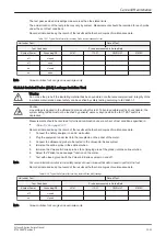
10.7 When there's too much Leakage Current...
10.7.1 AC/DC fails
Where applicable, check the AC/DC adapter and its cable. Replace a new one if any portion is defective.
10.7.2 Chassis fails
Check the ground on the power cord and plug for continuity. Ensure the ground is not broken, frayed, or
intermittent. Replace any defective part.
Tighten all grounds. Ensure star washers are under all ground studs. Inspect wiring for bad crimps, poor
connections, or damage.
Test the wall outlet; verify it is grounded and free of other wiring abnormalities. Notify the user or owner to
correct any deviations. As a work around, check the other outlets to see if they could be used instead.
Note
No outlet tester can detect the condition where the white neutral wire and the green grounding wire are
reversed. If later tests indicate high leakage currents, this should be suspected as a possible cause and the
outlet wiring should be visually inspected.
10.7.3 Probe fails
Test another probe to isolate if the fault lies with the probe or the system.
Note
Each probe will have some amount of leakage, dependent on its design. Small variations in probe leakage
currents are normal from probe to probe. Other variations will result from differences in line voltage and test
lead placement. The maximum allowable leakage current for body surface contact probe differs from inter-
cavity probe. Be sure to enter the correct probe type in the appropriate space on the check list.
Test the probe in another connector to isolate if the fault lies with the probe or the system. If excessive
leakage current is slot dependent, inspect the system connector for bent pins, poor connections, and ground
continuity.
If the problem remains with the probe, replace the probe.
10.7.4 Peripheral fails
Tighten all grounds. Ensure star washers are under all ground studs.
Inspect wiring for bad crimps, poor connections, or damage.
10.7.5 Still fails
If all else fails, begin isolation by removing the probes, external peripherals, then the on board ones, one at a
time while monitoring the leakage current measurement.
In case of using an UPS (Uninterruptible Power Supply), perform the tests in the “Electrical Safety tests”
section without using the UPS (i.e. directly connect the Voluson E-Series system to the AC wall outlet). If this
leads to a pass result, the specific UPS must no longer be used.
10.7.6 New Voluson E-Series system
If the leakage current measurement tests fail on a new Voluson E-Series system and if situation can not be
corrected, submit a Safety Failure Report to document the problem. Remove Voluson E-Series system from
operation.
10.7.7 ECG fails
Inspect cables for damage or poor connections.
Care and Maintenance
10-22
Voluson E-Series Service Manual
KTD106657 Revision 2
Summary of Contents for H48681XB
Page 11: ...Introduction Voluson E Series Service Manual KTD106657 Revision 2 1 3 ...
Page 12: ...Introduction 1 4 Voluson E Series Service Manual KTD106657 Revision 2 ...
Page 13: ...Introduction Voluson E Series Service Manual KTD106657 Revision 2 1 5 ...
Page 14: ...Introduction 1 6 Voluson E Series Service Manual KTD106657 Revision 2 ...
Page 15: ...Introduction Voluson E Series Service Manual KTD106657 Revision 2 1 7 ...
Page 16: ...Introduction 1 8 Voluson E Series Service Manual KTD106657 Revision 2 ...
Page 17: ...Introduction Voluson E Series Service Manual KTD106657 Revision 2 1 9 ...
Page 365: ......
Page 366: ...GE Healthcare Austria GmbH Co OG Tiefenbach 15 4871 Zipf Austria www gehealthcare com ...


