background image

3.13.4 InSite ExC Configuration

Prerequisites for InSite Setup

If not already available, collect the following information from the hospital network administrator:
1.

Proxy Server, if necessary
__________ / __________ / __________ / __________ and Port ________

2.

Proxy Authentication, if necessary
User ____________________________________ and Password

_________________________________________

Configuration Steps

1.

Enter the Common Service Desktop (CSD).

Note

There are different possibilities to access the Common Service Desktop and its available features; see

Section 5.12.2 "Access / Security" on page 5-39 

.

2.

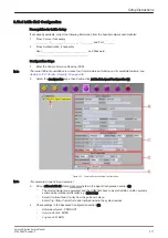
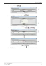
Select the 

Configuration

 page, then double-click 

InSite ExC Agent Configuration

 (A).

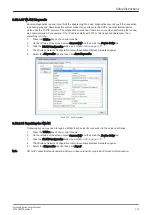
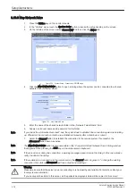
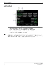
Figure 3-75  Common Service Desktop - Configuration

Note

This example shows fictional numbers!

3.

Fill out at least all bold stated mandatory fields in the Agent Configuration section (B).

-

The 

Device Name

 (pre-populated) and the 

CRM

 field have to be prefix KE6 or KE8 + systems

serial number without prefix letter; e.g. KE810026.

-

Select 

Continent

 and 

Country

 from the pull-down menu.

-

Enter 

City

State

Postal Code

 and 

Institution

 where the system resides.

4.

Check settings in the Advanced Configuration section (C).

-

Enterprise Server 

- PRODUCT

-

Service Center 

- EURO

-

Log Level 

- WARN

Setup Instructions

Voluson E-Series Service Manual
KTD106657 Revision 2

3-77

Summary of Contents for H48681XB

Page 1: ...COVER FM P R E L I M I N A R Y 0123 Voluson E Series BT13 5 Service Manual English English Voluson E6 Voluson E8 Voluson E8 Expert with Software version EC250 14 x x BT13 5 Document Number KTD106657 Revision 2 2013 2015 by General Electric ...

Page 2: ...ory Revision Date Reason for change MV April 2013 Preliminary Release 1 December 2013 Initial Release 2 October 2015 General Update and Improvement new parts i ii Voluson E Series Service Manual KTD106657 Revision 2 ...

Page 3: ...1 25 1 6 3 Electrostatic Discharge ESD Prevention 1 25 1 7 Customer Assistance 1 26 1 7 1 Contact Information 1 26 1 7 2 System Manufacturer 1 27 Chapter 2 Site Preparation 2 1 General Requirements 2 2 2 1 1 Environmental requirements 2 2 2 1 2 Electrical Requirements 2 2 2 1 3 EMI Limitations 2 3 2 1 4 Environmental Requirements for Probes 2 4 2 1 5 Time and Manpower Requirements 2 4 2 1 6 System...

Page 4: ... of Printer Settings 3 51 3 6 7 Remote Control Selection 3 57 3 7 System Configuration 3 58 3 7 1 System Setup 3 58 3 7 2 Measure Setup 3 61 3 8 On board optional Peripherals 3 62 3 9 External I O Connectors 3 64 3 9 1 External I O Pin Outs 3 65 3 9 2 Video Specification 3 66 3 9 3 External Cables Maximum Lengths 3 66 3 10 Available Probes 3 66 3 11 Software Option Configuration 3 67 3 12 Connecti...

Page 5: ...iption of Software Options 5 12 5 1 5 Description of Hardware Options 5 18 5 1 6 Data Location 5 19 5 2 FrontEnd Processor 5 20 5 2 1 RTF Probe Control Board 5 21 5 2 2 RSE Pencil Probe Board optional 5 21 5 2 3 RFM RF Interface Beamformer FE Mainboard 5 21 5 2 4 RSX Beamformer Receiver Transmitter Extension Board 5 21 5 3 BackEnd Processor 5 22 5 3 1 PC Motherboard 5 23 5 3 2 Hard Disk Drive HDD ...

Page 6: ...t for Service RFS 7 5 7 3 Check Point Voltages 7 7 7 3 1 User Interface Status LEDs 7 7 7 3 2 Power Supply RSP Status LEDs 7 7 7 4 Screen Captures and Logs 7 8 7 4 1 Capturing a Screen 7 8 7 4 2 Export Log s and System Data 7 9 7 5 Remote Access to the Service Platform 7 11 7 5 1 General 7 11 7 5 2 How the Customer enables disables Disruptive Mode and VCO 7 12 7 6 Common Service Desktop CSD 7 13 7...

Page 7: ...y Installation Procedure 8 21 8 12 Replacement of the Trackball Ring 8 21 8 12 1 Trackball Ring Replacement Procedure 8 21 8 13 Replacement of Key Caps by special native language keys 8 22 8 13 1 Key Caps Removal Procedure 8 22 8 13 2 Key Caps Installation Procedure 8 22 8 14 Replacement of the Caps for TGC Sliders and or Rotation Digipots 8 23 8 14 1 Caps for TGC Sliders and or Rotation Digipots ...

Page 8: ...ecks 10 5 10 4 2 Functional Checks 10 5 10 4 3 Physical Inspection 10 7 10 4 4 Cleaning 10 8 10 4 5 Probe Maintenance 10 8 10 5 Using a Phantom 10 9 10 6 Electrical Safety Tests 10 10 10 6 1 Safety Test Overview 10 10 10 6 2 Leakage Current Limits 10 11 10 6 3 Outlet Test Wiring Arrangement USA Canada 10 13 10 6 4 Grounding Continuity 10 14 10 6 5 Chassis Leakage Current Test 10 15 10 6 6 Isolated...

Page 9: ...portant Precautions 1 2 1 2 Legal Notes 1 10 1 3 Purpose of this Service Manual 1 11 1 4 Important Conventions 1 15 1 5 Safety Considerations 1 19 1 6 EMC EMI and ESD 1 25 1 7 Customer Assistance 1 26 Note Under consideration of general maintenance requirements a minimum lifetime of 7 years for the equipment and 5 years for the probes may be expected To maintain the safety and performance of the u...

Page 10: ...1 1 Important Precautions Translation Policy Introduction 1 2 Voluson E Series Service Manual KTD106657 Revision 2 ...

Page 11: ...Introduction Voluson E Series Service Manual KTD106657 Revision 2 1 3 ...

Page 12: ...Introduction 1 4 Voluson E Series Service Manual KTD106657 Revision 2 ...

Page 13: ...Introduction Voluson E Series Service Manual KTD106657 Revision 2 1 5 ...

Page 14: ...Introduction 1 6 Voluson E Series Service Manual KTD106657 Revision 2 ...

Page 15: ...Introduction Voluson E Series Service Manual KTD106657 Revision 2 1 7 ...

Page 16: ...Introduction 1 8 Voluson E Series Service Manual KTD106657 Revision 2 ...

Page 17: ...Introduction Voluson E Series Service Manual KTD106657 Revision 2 1 9 ...

Page 18: ...ies with equivalent training or licensed electricians to perform electrical servicing on the equipment Omissions errors If there are any omissions errors or suggestions for improving this documentation please contact the GE Healthcare Austria GmbH Co OG Service Documentation group with specific information listing the system type manual title part number revision number page number and suggestion ...

Page 19: ...guage policy for GE s service documentation the omission errors and the legal information are included in the beginning of this chapter chapter 1 Table 1 1 Contents in this service manual Chapter Number and Title Description Chapter 1 Introduction Contains a content summary and warnings Chapter 2 Site Preparation Contains pre installation requirements Chapter 3 Setup Instructions Contains setup an...

Page 20: ...Description BT version H48681XC Voluson E8 BT13 5 H48691JT Upgrade Voluson E8 BT13 5 to Voluson E8 Expert BT13 5 BT13 5 Table 1 4 Voluson E8 Expert model designations Part Number Description BT version H48681XD Voluson E8 Expert BT13 5 Table 1 5 Voluson E8 Expert Limited Edition model designations Part Number Description BT version H48681XE Voluson E8 Expert Limited Edition BT13 5 Introduction 1 1...

Page 21: ... 5 Voluson E8 Voluson E8 Expert systems with Serial Number D22001 BT13 5 Voluson E8 Voluson E8 Expert systems with Software version EC250 Ext x 14 x x BT13 5 Voluson E8 Expert Limited Edition systems with Serial Number D82001 BT13 5 Voluson E8 Expert Limited Edition systems with Software version EC250 Ext x 14 x x BT13 5 Introduction Voluson E Series Service Manual KTD106657 Revision 2 1 13 ...

Page 22: ... side panel 1 3 4 Purpose of Operator Manual s The operator manuals should be fully read and understood before operating the Voluson E Series system and also kept near the system for quick reference The online versions of the operator manual is available via the Help function F1 key on Voluson E Series control console The translated online user manuals are available on a CD ROM delivered with the ...

Page 23: ...nt graphical icons symbols may be used to make you aware of specific types of hazards that could cause harm Even if a symbol isn t used in this manual it is included for your reference Danger Indicates the presence of a hazard that will cause severe personal injury or death if the instructions are ignored Warning Indicates the presence of a hazard that can cause severe personal injury and property...

Page 24: ...are of specific procedures that should be followed Table 1 6 Standard icons that indicates that a special procedure is to be used Avoid Static Electricity Tag and Lock Out Wear Eye Protection Wear Hand Protection Wear Foot Protection 1 4 3 Product Labels and Icons The following table describes the purpose and location of labels safety icons and other important information provided on the equipment...

Page 25: ...e symbol IEC 60417 5336 identifies a defibrillation proof type CF applied part complying with IEC 60601 1 front side of the ECG preamplifier DANGER Risk of explosion used in The system is not designed for use with flammable anesthetic gases Indicated in the Service Manual This precaution is intended to prevent injury that may result if one person attempt to move the system considerable distances o...

Page 26: ...y RSP On Off or Standby CAUTION System shutdown using this button DOES NOT disconnect the Voluson E Series from mains voltage ON OFF Standby button on control console Mains ON Indicates the power on position of the mains power switch rear of system at mains switch on power supply RSP Protective Earth Indicates the protective earth grounding terminal rear of system at mains switch on power supply R...

Page 27: ... some metal surfaces may be warm enough to pose a potential heat hazard if touched even while in shutdown mode Warning Do not substitute parts or modify the system Because of the danger of introducing additional hazards ONLY install GE Healthcare Austria GmbH Co OG approved parts DO NOT perform any unauthorized modification of the system Warning Risk of electrical shock Beware that the main power ...

Page 28: ...n inclines Do not move the system sideways or diagonally Failure to follow the precautions could result in injury uncontrolled motion and costly damage Warning Ultrasound systems and probes are highly sensitive medical instruments that can easily be damaged by improper handling Use care when handling and protect from damage also when not in use Do not use a damaged or defective ultrasound system o...

Page 29: ...connecting Note For detailed information on handling probes refer to the Voluson E Series Basic User Manual and the care card supplied with the probe 1 5 5 Auxiliary Devices Safety Caution Power supplies for additional equipment MUST comply with IEC 60601 1 Caution Do not attempt to use different peripherals and accessories brand and model connected via USB port other than approved and provided by...

Page 30: ...te The system integrator any person connecting the medical device to other devices is responsible that connections are safe If in doubt consult the technical service department or your local representative Caution The leakage current of the entire system including any all auxiliary equipment must not exceed the limit values as per EN60601 1 1 IEC60601 1 1 respectively other valid national or inter...

Page 31: ...em Serial Number 10 TUEV NRTL Certification mark 15 GOST R label 1 5 7 Dangerous Procedure Warnings Warnings such as the examples below precede potentially dangerous procedures throughout this manual Instructions contained in the warnings must be followed Danger Dangerous voltages capable of causing death are present in this system Use extreme caution when handling testing and adjusting Warning If...

Page 32: ...decontaminated prior to shipment Under no circumstance should a part or equipment with visible body fluids be taken or shipped from a clinic or site for example body coils or and ultrasound probe The purpose of the regulation is to protect employees in the transportation industry as well as the people who will receive or open this package Note The US Department of Transportation DOT has ruled that...

Page 33: ...iated emission limits and to immunity from electrostatic discharge radiated and conducted RF fields magnetic fields and power line transient requirements as mentioned in IEC60601 1 2 Note For CE Compliance it is critical that all covers screws shielding gaskets mesh clamps are in good condition installed tightly without skew or stress Proper installation following all comments noted in this servic...

Page 34: ... or appropriate support resource as listed below Note Prepare vital system information see Section 7 1 on page 7 2 before you call System Type System Serial number also visible on label on back of the system Application Software version Backup version additional information about installed software Figure 1 3 phone numbers for customer assistance Introduction 1 26 Voluson E Series Service Manual K...

Page 35: ...em manufacturer Manufacturer Telephone FAX GE Healthcare Austria GmbH Co OG Austria GmbH Co OG Tiefenbach 15 A 4871 Zipf Austria Europe 43 0 7682 3800 0 43 0 7682 3800 47 Introduction Voluson E Series Service Manual KTD106657 Revision 2 1 27 ...

Page 36: ...This page was intentionally left blank Introduction 1 28 Voluson E Series Service Manual KTD106657 Revision 2 ...

Page 37: ...and prepare for the installation of a Voluson E Series system Included are descriptions of the facility and electrical needs to be met by the purchaser Content in this chapter 2 1 General Requirements 2 2 2 2 Facility Needs 2 6 Voluson E Series Service Manual KTD106657 Revision 2 2 1 ...

Page 38: ...ted power and ground for the proper operation of its Ultrasound equipment This dedicated power shall originate at the last distribution panel before the system The Ultrasound will function on voltages from 100 240 Volts and 50 or 60 Hz However if using 220 volt power in North America then a center tapped power source is required Sites with a mains power system with defined Neutral and Live The ded...

Page 39: ... plug or with the wrong plug you must contact your GE dealer or the installation engineer must supply what is locally required 2 1 3 EMI Limitations Ultrasound systems are susceptible to Electromagnetic Interference EMI from radio frequencies magnetic fields and transients in the air or wiring They also generate EMI The Voluson E Series system complies with limits as stated on the EMC label Howeve...

Page 40: ...e ferrite beads and other shielding Also cable length material and routing are all important do not change from what is specified Take care with cellular phones Cellular phones may transmit a 5 V m signal that could causes image artifacts Properly route peripheral cables Do not allow cables to lie across the top of the card rack or hang out of the peripheral bays Loop the excess length for periphe...

Page 41: ...onitor and peripherals Height Width Depth Weight 1520 mm 59 9 inch 1320 mm 52 0 inch 1120 mm 44 1 inch 580 mm 22 8 inch 1160 mm 45 6 inch 960 mm 37 8 inch 130 kg 286 6 lbs maximum at normal monitor position control console is lifted and moved forwards to the maximum minimum at normal monitor position no control console lifted or forwards movement absolute minimum monitor flapped down 2 1 6 2 Acous...

Page 42: ...d in the sales contract Note All electrical installations that are preliminary to the positioning of the equipment at the site prepared for the equipment must be performed by licensed electrical contractors Other connections between pieces of electrical equipment calibrations and testing must also be performed by qualified personnel The products involved and the accompanying electrical installatio...

Page 43: ... of network option An active network outlet in the vicinity of the ultrasound system A network cable of appropriate length regular Pin to Pin network cable An IT administrator who will assist in configuring the system to work with your local network A fixed IP address is required Refer to the form provided in Figure 3 81 for network details that are required Note All relevant preliminary network p...

Page 44: ...n this manner frees up the on board monitor and peripherals enabling viewing to be done while scanning continues With DICOM images can be archived stored and retrieved faster easier and at a lower cost 2 2 4 4 DICOM Option Pre installation Requirements To configure the Voluson E Series ultrasound system to work with other network connections the network administrator must provide some necessary in...

Page 45: ...chapter 3 1 Setup Reminders 3 2 3 2 Receiving and Unpacking the System 3 5 3 3 Preparing for Setup 3 7 3 4 Connection of Auxiliary Devices 3 9 3 5 Completing the Setup 3 39 3 6 Printer Installation 3 44 3 7 System Configuration 3 58 3 8 On board optional Peripherals 3 62 3 9 External I O Connectors 3 64 3 10 Available Probes 3 66 3 11 Software Option Configuration 3 67 3 12 Connectivity Setup 3 67...

Page 46: ...rvicing and troubleshooting 3 1 2 1 Moving Lifting the System Note For important safety considerations see Section 1 5 3 Mechanical Safety on page 1 20 Figure 3 1 lifting the system How to lift the system 1 Preparation Disconnect all probes and transport them separately Disconnect the ECG cable if applicable and transport it separately Ensure all peripheral devices printer are firmly fixed within ...

Page 47: ...hrs 8 6 4 2 0 0 0 0 0 0 0 2 4 6 8 10 12 14 16 18 20 3 1 2 3 Control Console Positioning If weight is placed on the control console UI in it s extended position the system could tip over Caution The system should not be moved with the control console UI extended Move the control console to it s centered and locked position for transport Caution Monitor mounting mechanism may break if not properly s...

Page 48: ... may be present Caution Two people should unpack the system because of its weight Two people are required whenever a part weighing 16kg 35 lb or more must be lifted Caution Do not wear the ESD wrist strap when you work on live circuits and more than 30 V peak is present Caution If the system is very cold or hot do NOT turn on its power until it has had sufficient time to acclimate to its operating...

Page 49: ...n alone could result in personal injury and or damage to the system Table 3 4 shipping cardboard dimensions and weight Description Height Width Depth Weight Voluson E Series incl peripherals and accessories 1500 mm 59 inch 800 mm 31 5 inch 1150 mm 45 3 inch 170 kg 375 lbs Weight is approximate and will vary depending upon the supplied peripherals Before unpacking the system Inspect the cardboard f...

Page 50: ...system such a way that packaging can be reused For warranty purposes storage of the above is required for one year from date of purchase Note If the shipping cardboard is damaged please inform the GE Healthcare Austria GmbH Co OG sales representative immediately Unpacking procedure Unpack the Voluson E Series ultrasound system and its optional peripherals and accessories according to the provided ...

Page 51: ...for bent or damaged pins on the connector and in the connector socket on the system Verify that the EMI fingers around the probe connector socket housing are intact Check the probe locking mechanism and probe switch 5 LCD Display Clean the LCD display by gently wiping with a dry soft lint free non abrasive folded cloth Inspect the monitor for scratches and raster burn 6 Fans Verify that the system...

Page 52: ...s and ceilings comprised of wood plaster or concrete which help prevent EMI Shield the system when operating it in the vicinity of radio broadcast equipment if necessary Do not operate mobile phones or other EMI emitting devices in the ultrasound room Verify that all EMI rules listed are followed The Voluson E Series system is approved for use in hospitals clinics and other environmentally qualifi...

Page 53: ...iary device Note It is impossible to attach a Black White printer a Color printer and a DVD USB video recorder within the system at the same time as there is not enough space for them all At the left shelf you can place either a Color printer or a DVD USB video recorder Note Only one recording device can be connected at a time to the Voluson E Series system Warning After each installation the leak...

Page 54: ... 1 Connecting the LCD Monitor Note The LCD Monitor comes pre installed with the system Figure 3 3 Connection Scheme LCD Monitor Setup Instructions 3 10 Voluson E Series Service Manual KTD106657 Revision 2 ...

Page 55: ...ftware drivers are pre installed for the designated printer only 6 After physical connection to the Voluson E Series system assign the printer to a remote key P1 P2 P3 and or P4 as described in Section 3 6 7 Remote Control Selection on page 3 57 7 Verify correct printer settings see Section 3 6 6 Adjustment of Printer Settings on page 3 51 Note The B W printer should be connected to the USB3 port ...

Page 56: ...3 4 2 1 Connection Scheme B W Printer Figure 3 4 Connection Scheme B W Printer Setup Instructions 3 12 Voluson E Series Service Manual KTD106657 Revision 2 ...

Page 57: ...mote Control Selection on page 3 57 6 Verify correct printer settings see Section 3 6 6 Adjustment of Printer Settings on page 3 51 Note The Color printer should be connected to the USB4 port of the Voluson E Series s PC part Location of the USB4 port depends on the installed PC Motherboard If in doubt refer to Section 5 4 on page 5 24 for detailed internal In Out cable routing If the printer driv...

Page 58: ...3 4 3 1 Connection Scheme Color Printer Figure 3 5 Connection Scheme Color Printer Setup Instructions 3 14 Voluson E Series Service Manual KTD106657 Revision 2 ...

Page 59: ...ment meets the requirements of the EN 60950 Standard Connection via Bluetooth Adapter The DeskJet Color Printer can be connected to an external non isolated power source The Bluetooth Adapter should be directly connected to the indicated USB port E on the RTB Distribution Board Bottom Note Please use the proper Bluetooth Printer Connection set see Section 9 10 2 Printers on page 9 34 Figure 3 6 Co...

Page 60: ...ia an USB cable Note If a DeskJet printer e g HP Officejet 100 is connected directly via an USB cable use the AC mains power outlet provided by the Voluson E Series system auxiliary output This ensures medical grade separation from AC mains Figure 3 7 Connection Scheme DeskJet Color Printer directly via USB cable Setup Instructions 3 16 Voluson E Series Service Manual KTD106657 Revision 2 ...

Page 61: ...gh cable is used The Network Color Laser Printer HP451 automatically reconfigures signals to yield expected results Connection directly to the Voluson E Series Physical connection 1 Connect the Color Laser Printer Connect the network cable to the Ethernet LAN connector on the Voluson E Series system The other end connect to the Ethernet connector of the Color Laser Printer Connect the power cable ...

Page 62: ...luson E Series system The other end connect to a hospital network wall outlet Connect the second network cable to the Ethernet connector of the Color Laser Printer The other end connect to a hospital network wall outlet Connect the power cable of the printer to an external non isolated power source 2 Install the Color Laser Printer as described in Section 3 6 4 on page 3 45 Figure 3 9 Connection S...

Page 63: ...power ON button on the recorder b Power On Boot Up the system as described in Section 4 2 1 on page 4 3 4 After physical connection to the Voluson E Series system a Adjust the DVD Recorder settings as described in Section 3 4 6 2 on page 3 22 b Check and if necessary change the Video Norm see Section 3 7 1 6 on page 3 60 c Check and if necessary change the Recorder Type see Section 3 7 1 8 on page...

Page 64: ... Scheme DVD Recorder DVD Recorder Connection at ADVANTECH Micro ATX PC Motherboard Figure 3 10 DVD Recorder connection ADVANTECH PC Motherboard Setup Instructions 3 20 Voluson E Series Service Manual KTD106657 Revision 2 ...

Page 65: ...DVD Recorder Connection at DFI Micro ATX PC Motherboard Figure 3 11 DVD Recorder connection DFI PC Motherboard Setup Instructions Voluson E Series Service Manual KTD106657 Revision 2 3 21 ...

Page 66: ...r Figure 3 12 keys on the front of the recorder 3 The Main Menu appears on the LCD screen of the DVD recorder Figure 3 13 Main Menu SETUP MENU highlighted 4 Press the button on the front of the recorder repeatedly until the SETUP MENU item is highlighted 5 Press the button The Setup Menu appears 6 Press the button on the front of the recorder repeatedly until REMOTE I F is highlighted Figure 3 14 ...

Page 67: ...16 Setup Menu MENU GRADE highlighted 7 Press the button and select ENHANCED 8 Press the button to exit the Menu Grade menu Note Now additional items are displayed in the Setup Menu 9 Press the button repeatedly until TV SYSTEM is highlighted Figure 3 17 Setup Menu TV SYSTEM highlighted 10 Press the button The TV System Sub menu appears 11 Select the appropriate video signal by pressing the or butt...

Page 68: ...utton The Region Code Menu appears 8 Select the appropriate region code by pressing the or button respectively To check the region code see Table 3 6 on page 3 24 9 Press the SET button C The message Now loading appears and the system starts to save the settings 10 When Power off appears on the display press the Power switch on the front of the DVD recorder to turn power off 11 Press the Power swi...

Page 69: ... the USB Video recorder b Turn ON the power of the Voluson E Series system 4 After physical connection to the Voluson E Series system a Check and if necessary change Ext Monitor setting to DVI see Section 3 7 1 7 on page 3 60 b Adjust the USB Video Recorder settings as described in Section 3 4 7 2 on page 3 27 Warning After each installation the leakage currents have to be measured according to IE...

Page 70: ...3 4 7 1 Connection Scheme USB Video Recorder Figure 3 19 USB Video Recorder connection Setup Instructions 3 26 Voluson E Series Service Manual KTD106657 Revision 2 ...

Page 71: ...ING 11 INPUT DVI SXGA 1 Press the O Enter button on the front of the USB video recorder for min 4 seconds 2 Press the or button to select SETTING and then press O Enter 3 Press the or button to select REC SETTING and then press O Enter 4 Press the or button to select INPUT and then press O Enter 5 Press the or button to select DVI SXGA and then press O Enter TOP MENU SETTING 01 REC SETTING 12 MODE...

Page 72: ...f the USB video recorder for min 4 seconds 2 Press the or button to select SETTING and then press O Enter 3 Press the or button to select REC OPTION and then press O Enter 4 Press the or button to select OVER WRITE and then press O Enter 5 Press the or button to select OFF and then press O Enter TOP MENU SETTING 02 REC OPTION 23 REMOTE Start Stop 1 Press the O Enter button on the front of the USB ...

Page 73: ...Network Adapter can be connected to any accessible USB port of the Voluson E Series Figure 3 20 Connection Scheme Wireless USB Network Adapter Note Connection is always the same no differences between PC Motherboard version of the Voluson E Series system Note After physical connection of the WLAN adapter to the Voluson E Series system follow the procedure described in Section 3 13 2 Wireless Netwo...

Page 74: ... system Caution A Secondary Patient Monitor MUST NEVER be connected to the Voluson E Series systems mains supply directly Always connect it to an appropriate Isolation Transformer see Section 9 10 4 on page 9 37 Figure 3 21 Connection Scheme VGA Image Resizer Note After physical connection of the VGA Image Resizer to the Voluson E Series system follow the procedure described in Section 3 4 9 1 Adj...

Page 75: ...g press either the Menu and key or the and key until the image reappears Try other settings that are supported by your monitor 2 Use high quality Video cables especially for longer distances High quality cables improve overall image quality due to lower sensitivity on electromagnetic interferences 3 Set Brightness Contrast for best and detailed image display a Press the Menu key select Picture Adj...

Page 76: ... Note Take your time to think about the best position of the monitor in your facilities Patients should be able to view the monitor easily and without having to bend or turn around 1 Power Off Shutdown the system as described in Section 4 2 2 on page 4 4 2 Connect the Secondary Monitor according to connection scheme see Figure 3 23 on page 3 33 3 After physical connection to the Voluson E Series s...

Page 77: ...3 4 10 1 Connection Scheme Secondary Patient Monitor Figure 3 23 Connection Scheme Secondary Monitor Setup Instructions Voluson E Series Service Manual KTD106657 Revision 2 3 33 ...

Page 78: ...Figure 3 24 Secondary Monitor connection via VGA Image Resizer Setup Instructions 3 34 Voluson E Series Service Manual KTD106657 Revision 2 ...

Page 79: ...ar of the system Note Connection is always the same no differences between PC Motherboard version of the Voluson E Series system After physical connection adjust the Footswitch as described in Section 3 7 1 9 on page 3 60 Figure 3 25 Connection Scheme Footswitch Setup Instructions Voluson E Series Service Manual KTD106657 Revision 2 3 35 ...

Page 80: ...er Note Connection is always the same no differences between PC Motherboard version of the Voluson E Series system Figure 3 26 Connection Scheme ECG preamplifier Setup Instructions 3 36 Voluson E Series Service Manual KTD106657 Revision 2 ...

Page 81: ...see Section 3 4 15 2 External USB Devices Disconnection on page 3 38 3 4 14 Connecting an external USB Hard disk Note Before connecting an USB device please read Section 3 4 15 General Remarks and Hints when using external USB Devices on page 3 38 An external HDD may be connected to an accessible USB port of the Voluson E Series system e g on back of control console An external USB Hard Disk Drive...

Page 82: ... Voluson E Series Basic User Manual 3 4 15 2 External USB Devices Disconnection Before an external USB device e g USB memory stick can be disconnected the system has to be informed about the removal of the device For this purpose press the USB key on the keyboard Caution Unplugging or ejecting USB devices without first stopping them can cause the system to crash and possibly result in loss of valu...

Page 83: ...stem from the electrical outlet always observe the safety precautions First unplug the main power cable from the wall outlet socket then from the system itself Remove by pulling on the cable connector Do not pull on the cable Caution The Voluson E Series requires all covers Do not operate this system unless all board covers and frame panels are securely in place to ensure optimal system performanc...

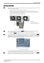
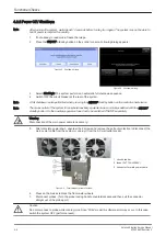
Page 84: ...cluding the Back end Processor starts and the operating system is loaded which then leads to activate the application software The system automatically performs an initialization sequence which includes the following Loading the operating system Running a quick diagnostic check of the system Detecting connected probes Figure 3 30 ON OFF standby button As soon as the software has been loaded the sy...

Page 85: ...Boot screen 3 BackEnd processor is turned ON and starts to load the software 4 The start screen is displayed on the monitor 5 Start up progress bars indicating software loading procedures are displayed on the monitor Figure 3 32 start up screen 6 The software initiates and sets up the FrontEnd electronics and the rest of the system incl clicking sound of relays on RTF board 7 The keyboard backligh...

Page 86: ...commonly switched with the ON OFF standby button So the auxiliary equipment need not to be switched ON OFF separately Warning Disconnection of the main power cable is necessary 5 After complete power down unscrew the 2 screws and remove the pull out protection to disconnect the main power cable from the system or unplug it from the AC wall outlet socket Figure 3 34 Circuit Breaker at rear of syste...

Page 87: ... lay the cable into the intended cable holder and close the door 6 Carefully position the probe cord so that it is free to move and is not resting on the floor Figure 3 35 probe connection 1 probe unlocked locking lever is in horizontal position 2 probe locked locking lever is in vertical position Caution Do not bend the probe cable acutely Fault conditions can result in electric shock hazard Do n...

Page 88: ...6 6 Adjustment of Printer Settings on page 3 51 4 Assign the printer to the remote keys P1 P2 P3 and or P4 see Section 3 6 7 Remote Control Selection on page 3 57 3 6 2 Installing the Digital Color Printer 1 Power Off Shutdown the system as described in Section 4 2 2 on page 4 4 2 Connect and install the printer as described in Section 3 4 3 on page 3 13 3 Verify correct printer settings see Secti...

Page 89: ... paper 6 Wait until the printer displays Ready Figure 3 36 printer controls 1 Power ON 5 Right 2 Display 6 OK 3 Status Indicators 7 Left 4 Cancel 8 Back 7 By means of the Printer Controls Left Right and OK set the TCP IP address to Automatic Figure 3 37 TCP IP Config Automatic 8 Press the Back button until the Printer displays Ready again 9 By means of the Printer Controls Left Right and OK print ...

Page 90: ...1 sid 101 SF 1 and extract files to CD or USB disk 12 Connect the USB stick to the Voluson E Series system or insert the CD into the drive 13 Press the Utilities key on the control console 14 In the Utilities menu touch the System Setup button to invoke the setup desktop on the screen 15 On the left side of the screen select Connectivity and then click the Peripherals tab 16 Click the Add Printer ...

Page 91: ...hen click Next Figure 3 41 the printer isn t listed 19 Check mark Connect to this printer 20 Enter http followed by the previously print out printer IPv4 Address e g 3 249 68 25 see Figure 3 39 on page 3 46 and then click Next Note This example shows fictional numbers Figure 3 42 enter printers IP Address Setup Instructions Voluson E Series Service Manual KTD106657 Revision 2 3 47 ...

Page 92: ... driver 22 Select HP Universal Printing PCL6 and then click OK to start the installation Figure 3 44 select proper printer 23 Confirm the following screen with Next 24 Remove the check mark at Set as the default printer and then click on Print a test page Note Please DO NOT yet click on Finish Figure 3 45 installation successful Setup Instructions 3 48 Voluson E Series Service Manual KTD106657 Rev...

Page 93: ... then click OK Figure 3 48 remove all check marks 28 Finally click on Finish see Figure 3 45 on page 3 48 29 Assign the printer to the remote keys P1 P2 P3 and or P4 see Section 3 6 7 Remote Control Selection on page 3 57 30 Assign the printer as Report Printer see Section 3 6 7 1 Report Printer Selection on page 3 57 31 Close all open windows select Save Exit and restart the system turn off and o...

Page 94: ...C Recorder Type selection 3 Report Printer selection 4 Click the Add Printer button Please read the displayed message carefully and click Yes if you have skills to do this 5 Click the Next button to start the Add Printer Wizard 6 After installation close all open windows select Save Exit and restart the system turn off and on the system 7 Verify correct printer settings see Section 3 6 6 Adjustmen...

Page 95: ...page 3 56 Warning After each installation the leakage currents have to be measured according to IEC 60601 1 UL 60601 1 IEC 62353 or other relevant standard 3 6 6 1 UP D897 UP D898MD Printer Settings 1 Call up the Printer Preferences see Section 3 6 6 Adjustment of Printer Settings on page 3 51 2 Select the Layout page and select Paper 960x1280 Orientation Portrait Interpolation Method Bilinear Fig...

Page 96: ...and exit Figure 3 52 P95D Printer settings 1 Brightness 0 2 Contrast 0 3 Sharpness 3 4 Gamma r5 2 Assign the printer to the remote keys P1 P2 P3 and or P4 see Section 3 6 7 Remote Control Selection on page 3 57 3 Activate USB serial number a Turn the printer OFF and wait 5 seconds b Press and hold the buttons COPY CONT and power on the printer When the Display changes to S1 the buttons can be rele...

Page 97: ...ct the Paper page and select Paper Size L large Orientation Landscape recommended when using large paper size Figure 3 53 Paper page 4 Save the adjusted printer settings with Apply and OK Close window and exit System Setup 5 Assign the printer to the remote keys P1 P2 P3 and or P4 see Section 3 6 7 Remote Control Selection on page 3 57 Setup Instructions Voluson E Series Service Manual KTD106657 R...

Page 98: ...large paper size High Speed check mark on Note Settings for paper size must match with the used paper large small and also the right color ink cartridge has to be used Otherwise you will get an error message at printing 3 Select the Graphics page From the Color Adjust pull down menu select 4 Color Balance Cyan 0 Magenta 0 Yellow 0 Figure 3 54 Paper Graphics page Setup Instructions 3 54 Voluson E S...

Page 99: ... X 50 Y 50 8 Adjustment by Color Color region Magenta Red Figure 3 56 Graphic page Gray Balance Adjustment by Color 9 Save the adjusted printer settings with Apply and OK Close window and exit System Setup 10 Assign the printer to the remote keys P1 P2 P3 and or P4 see Section 3 6 7 Remote Control Selection on page 3 57 Setup Instructions Voluson E Series Service Manual KTD106657 Revision 2 3 55 ...

Page 100: ...a 0 Yellow 0 Gamma Select Gamma 1 Figure 3 57 Graphics page Color Balance Gamma Select Color Correction set Printer Hardware Color Correction Lightness Sharpness 7 or 8 Dark 0 Gamma 12 Light 8 Figure 3 58 Graphic page Color Correction Lightness 4 Save the adjusted printer settings with Apply and OK Close window and exit System Setup 5 Assign the printer to the remote keys P1 P2 P3 and or P4 see Se...

Page 101: ...emote Buttons Select the desired remote control button b Select Printer Check mark and select the desired Printer for the remote control button c Recorder Control Check mark this item to use the selected P key for Recorder Control Note Optionally the Printer Remote Control can be done by the Foot switch see Figure 3 49 on page 3 50 2 Detailed Setup tab a If it is desired check mark Use Report Prin...

Page 102: ...COM Archive and Network configuration nodes Button Configuration adjust assignment of Remote keys P1 P2 P3 e g Printer selection Drives USB and Network drives stop devices map network drive erase CD System Configuration Save Load Scan Settings Small Backup Save Load Delete Full System Configuration Image Archive Save Load Image Archive Note For further details refer to the Voluson E Series Basic U...

Page 103: ... Save Exit 3 7 1 3 How to enter Clinic Name 1 Invoke System Setup as described in Section 3 7 1 1 on page 3 58 2 On the left side of the screen select General and then click the General Settings tab 3 Select the text box to enter a new Clinic Name with the keyboard 4 Close the Service page with Save Exit The clinic name will be copied into the Clinic Name ID field of the information header 3 7 1 4...

Page 104: ...L 50Hz or NTSC 60Hz see Figure 3 49 on page 3 50 4 Close the Service page with Save Exit and restart the system 3 7 1 7 How to change Ext Monitor Video Signal 1 Invoke System Setup as described in Section 3 7 1 1 on page 3 58 2 On the left side of the screen select Connectivity and then click the Peripherals tab 3 If not currently selected click the proper field see Figure 3 49 on page 3 50 4 Clos...

Page 105: ...ize Font size and color of measure results position of measure results for different modes etc Note For further details refer to the Voluson E Series Basic User Manual 3 7 2 1 How to invoke Setup Procedure 1 Press the Utilities key on the control console 2 In the Utilities menu touch the Measure Setup button to invoke the setup desktop on the screen Note In general operations are done with the tra...

Page 106: ...k USB Port Table 9 11 Belkin Belkin DVD Recorder SONY DVO 1000MD PAL NTSC PAL NTSC Table 9 10 USB Video Recorder VISK MR 200 USB Port Table 9 10 ECG Preamplifier NORAV MAN10 USB Port Table 9 12 MAN30 USB Flash Memory device SanDisk Cruzer Micro USB Port Table 9 12 USB external Hard Disk Drive Fujitsu Handydrive USB Port Table 9 12 Wireless Adapter WLAN Netgear WG111v3 USB Port Table 9 12 Footswitc...

Page 107: ...t be possible that some probes options or features are NOT available in some countries at the time of release of this Service Manual Setup Instructions Voluson E Series Service Manual KTD106657 Revision 2 3 63 ...

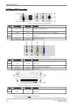
Page 108: ...nnectors on back of console Item Connector Name Table Number Description 1 USB Table 3 10 USB 2 0 port 2 3 DVI Monitor Table 3 13 Monitor DVI Digital Visual Interface 4 Monitor Power Table 3 12 Monitor Power Figure 3 64 External I O connectors next to DVD or DVR drive Item Connector Name Table Number Description 1 USB 5 Table 3 10 USB 2 0 port 2 5 If the USB cables need to be replaced use item 722...

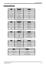
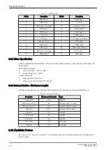
Page 109: ...ER RD Ethernet TD others NC no connection Table 3 10 USB 2 0 connectors Pin No Output Signal Description 1 VCC USB Power Supply 2 Data USB Data 3 Data USB Data 4 GND USB Power Ground Table 3 11 S Video OUT connector 4 pin Pin No Output Signal Description 1 SVIDEO OUT IN YG Y Luma GND 2 SVIDEO OUT IN CG C Chroma GND 3 SVIDEO OUT IN Y Y Luma Signal 4 SVIDEO OUT IN C C Chroma Signal Table 3 12 Monito...

Page 110: ...sible resolution 1280 x 1024 screen refresh rate 60Hz S Video connector Type separate Video Y C Video modes PAL 50Hz NTSC 60Hz 3 9 3 External Cables Maximum Lengths Table below shows maximum permitted cable length of external cables according to IEC60601 1 2 Table 3 14 maximum cable lengths Description Maximum Cable Length Type Probe cable 2 5 m shielded USB cable port 2 0 5 m shielded USB2 0 or h...

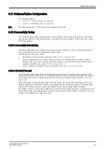
Page 111: ...ecause no network is available see Section 3 12 1 4 on page 3 69 Voluson E Series and DICOM server in a network see Section 3 12 1 5 on page 3 69 3 12 1 1 Dataflow Concept Communication between the Voluson E Series ultrasound system and other information providers on the network takes the form of data flows Each dataflow defines the transfer of patient information from either an input source to th...

Page 112: ...tc A remote database is used for patient archiving Images are also stored to a remote archive Search in the DICOM Modality Worklist the patient found is copied into local database The patient information and the examination results are stored to the local database Images are stored to a DICOM server and to an image network volume on the local hard drive Setup Instructions 3 68 Voluson E Series Ser...

Page 113: ...export backup patient data as well as measurements at least once a month Physical Connection No network connection needed 3 12 1 5 Connection between Voluson E Series and DICOM Server In this configuration the Voluson E Series is configured to work with a DICOM server in a network environment Usually this will be the hospital network Images are first saved on the local image buffer on the system A...

Page 114: ...screen select Connectivity and then click the Device Setup tab 4 Click the TCP IP Configuration button read the message and confirm with Yes Figure 3 65 TCP IP Configuration 5 The Internet Protocol TCP IP Properties dialog page appears Note This example shows fictional numbers Figure 3 66 Internet Protocol TCP IP 1 You can get IP and DNS settings assigned automatically if your network supports thi...

Page 115: ... touch the System Setup button to invoke the setup desktop on the screen 4 On the left side of the screen select Connectivity and then click the Device Setup tab 5 Click the WLAN Configuration button see Figure 3 65 on page 3 70 6 The Wireless Network Configuration tool with available Wireless Networks appear Figure 3 67 Wireless Networks Connect 7 Check box Enable Wireless Connection 8 Highlight ...

Page 116: ... select Connectivity and then click the Device Setup tab 3 Click the WLAN Configuration button see Figure 3 65 on page 3 70 4 The Wireless Network Configuration tool with available Wireless Networks appear 5 Click Refresh 3 13 2 5 Setting a WLAN Network as Non Preferable When you make a WLAN non preferable you disconnect the network from the system and delete all connection settings from the syste...

Page 117: ...left side of the screen select Connectivity and then click the Device Setup tab 3 Click the WLAN Configuration button see Figure 3 65 on page 3 70 4 The Wireless Network Configuration tool with available Wireless Networks appear 5 Select the Security tab and then click Customize Figure 3 69 Security Customize 6 Customize the following information Network Name SSID Check box Connect even if Network...

Page 118: ...on tool with available Wireless Networks appear 5 Select the Properties tab Figure 3 70 Properties 6 Click Available Channels 3 13 2 9 Monitoring the WLAN If there are wireless network communication issues you can monitor the wireless connection to see if it is dropping out and recovering periodically This can effect throughput 1 Press the Utilities key on the control console 2 On the left side of...

Page 119: ...e Figure 3 65 on page 3 70 4 The Wireless Network Configuration tool with available Wireless Networks appear 5 Select the Diagnostics tab and then click Run Diagnostics Figure 3 72 Run Diagnostics 3 13 2 11 Repairing the WLAN Occasionally you may need to repair a WLAN that has lost its connection to the Voluson E Series 1 Press the Utilities key on the control console 2 On the left side of the scr...

Page 120: ...after a shutdown or reboot 7 Select the Connect button to establish the connection to the remote system If successful the Disconnect button becomes active Note The Map Network Drive button is also accessible in the Connect USB and Network Drives dialog window that appears when pressing the USB key on the alphanumeric keyboard Note If there is an error during the connection a warning message appear...

Page 121: ...tion 5 12 2 Access Security on page 5 39 2 Select the Configuration page then double click InSite ExC Agent Configuration A Figure 3 75 Common Service Desktop Configuration Note This example shows fictional numbers 3 Fill out at least all bold stated mandatory fields in the Agent Configuration section B The Device Name pre populated and the CRM field have to be prefix KE6 or KE8 systems serial num...

Page 122: ...utomatically 6 Click the Submit Changes button E and then close the page 7 Reboot 8 Reenter the Common Service Desktop CSD 9 Confirm that Service Connectivity is Configured and Checked Out in the Home page If the system indicates Checked Out you can be confident that the system has registered correctly If required verify further connectivity e g remote connectivity using your account 10 Close the ...

Page 123: ...Figure 3 78 confirm with Add User 6 Check mark the appropriate user and then click Set Default Machine Contact 5 Figure 3 79 set User as Default Color of the selected user turns from BLACK to RED 6 The permanent user is created 7 Close the window Setup Instructions Voluson E Series Service Manual KTD106657 Revision 2 3 79 ...

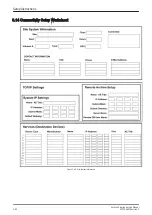
Page 124: ...3 14 Connectivity Setup Worksheet Figure 3 80 Site System Information Setup Instructions 3 80 Voluson E Series Service Manual KTD106657 Revision 2 ...

Page 125: ...Figure 3 81 Worksheet for DICOM Network Information Setup Instructions Voluson E Series Service Manual KTD106657 Revision 2 3 81 ...

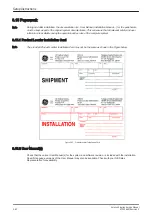
Page 126: ... 15 1 Product Locater Installation Card Note The provided Product Locater Installation Card may not be the same as shown in the Figure below Figure 3 82 Product Locater Installation Card 3 15 2 User Manual s Check that the correct User Manual s for the system and software revision is included with the installation Specific language versions of the User Manual may also be available Check with your ...

Page 127: ...eneral Procedure 4 2 4 3 Functional Checks 4 8 4 4 Backup and Restore Database Preset Configurations and Images 4 29 4 5 Software Configuration Checks 4 42 4 6 Peripheral Checks 4 43 4 7 Mechanical Function Checks 4 44 4 8 Site Log 4 45 Note Most of the information pertaining to this Functional Checks chapter is found in the Voluson E Series Basic User Manual see Section 9 11 System Manuals on pag...

Page 128: ...uires all covers Do not operate the Voluson E Series system unless all board covers and frame panels are securely in place The covers are required for safe operation good system performance and cooling purposes When covers are removed EMI may be present Lockout Tagout Requirements For USA only Follow OSHA Lockout Tagout requirements by ensuring you are in total control of the Power Cable on the sy...

Page 129: ...cluding the Back end Processor is in standby mode 5 Hold down the ON OFF standby button see Figure 4 2 below on the control console for 3 seconds Note The mains outlet of the system for peripheral auxiliary equipment are commonly switched with the ON OFF standby button The power switch of any attached printer s needs to be in ON position before starting the system However be aware some auxiliary e...

Page 130: ...commonly switched with the ON OFF standby button So the auxiliary equipment need not to be switched ON OFF separately Warning Disconnection of the main power cable is necessary 5 After complete power down unscrew the 2 screws and remove the pull out protection to disconnect the main power cable from the system or unplug it from the AC wall outlet socket Figure 4 4 Circuit Breaker at rear of system...

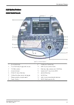
Page 131: ...ontrols 11 Mode keys rotary controls used in 3D 4D Mode 4 screen format keys 12 keyboard and F1 key to invoke EUM 5 3D and 4D Volume Mode keys 13 additional Mode keys 6 HR Zoom Pan Zoom rotary control toggle 14 DVD VCR key 7 Remote control keys programmable 15 button for control console height adjustment 8 Freeze Run key 16 ON OFF Standby power button Functional Checks Voluson E Series Service Man...

Page 132: ...lication the active one is highlighted 4 Additional functions which are supported by the selected Mode Note Different menus are displayed depending on which Touch Panel Menu and which Mode is selected At the bottom of the Touch Panel there are combination rotary dial push buttons and flip switch controls The functionality of these controls changes depending upon the currently displayed menu Functi...

Page 133: ...Frame rate 20 6 Mechanical Index 21 Message Area 7 Thermal Index 22 Clipboard History 8 Sonographers Name 23 Current Clipboard 9 Hospital Name Identification 24 Bodymarks 10 Date 25 Depth scale markers 11 Time 26 Gray scale wedge 12 Image Info 27 Focal zones marker 13 TGC curve 28 Orientation marker 14 Image area 29 Second patient ID 15 Measurement results Functional Checks Voluson E Series Servic...

Page 134: ...ge 4 17 3D Static 4D Real Time 4D Biopsy VCI Volume Contrast Imaging A Plane C Plane and VCI Static STIC Spatio Temporal Image Correlation T U I Tomographic Ultrasound Imaging VOCAL II It might be possible that some probes options or features are NOT available in some countries at the time of release of this Service Manual Note Some software may be considered standard depending upon system configu...

Page 135: ...rame rate are automatically optimized 5 Screen Format Dual Quad Press this keys to change the display Mode from Single to Dual or Quad display mode Press the Single format key or the 2D Mode key to change from Dual or Quad to Single display 6 2D Automatic Optimization Pressing the Auto key causes automatic optimization of the gray scale to enhance the contrast resolution Pressing again optimizatio...

Page 136: ...steering the ultrasound lines in the border of the probe 18 Image Orientation Use the left right respectively the up down keys on the Touch panel to alternate the image orientation 19 Angle Use this control to select a part of interest of the 2D image The advantage of the decreased field of view is an increased 2D frame rate due to the smaller sector width 20 ß View This function allows the adjust...

Page 137: ...t subtle tissue differences and boundaries by enhancing the gray scale differences corresponding to the edges of structures 32 Reject Selects a level below which echoes will not be amplified an echo must have a certain minimum amplitude before it will be processed Note For further details refer to the Voluson E Series Basic User Manual 4 3 2 Additional optional Operating Modes 4 3 2 1 B Flow B Flo...

Page 138: ... XTD View Main Menu Note For further details refer to the Voluson E Series Basic User Manual 4 3 2 3 Coded Contrast Imaging Coded Contrast Imaging On Off switch Press the Contrast key to activate deactivate the Coded Contrast Imaging mode Figure 4 11 Contrast Main and Contrast Sub Menu Note For further details refer to the Voluson E Series Basic User Manual Functional Checks 4 12 Voluson E Series ...

Page 139: ...rmat e g In the Dual format two defined distances can be displayed at the same time 7 Speed By touching up or down four different sweep speeds can be selected 8 Invert Invert of the M Mode image Function is only available with endovaginal probes 9 Frequency resp Harm Frequ Common with Frequency 10 Display Format For selection of different rations of display format 11 Reject It determines the ampli...

Page 140: ... selected probe is capable for the Continuous Wave Doppler Mode Figure 4 14 PW Main and PW Sub Menu Table 4 3 Spectral Doppler Mode PW CW Functions Step Task Expected Results 1 Gate Position and Gate Size Adjust the Gate Position resp Size with the trackball in the 2D Single image The upper trackball key changes from Gate position to Gate size 2 Activation of Doppler Mode Press the right trackball...

Page 141: ...or selection of the required transmit frequency 15 Scale Unit To select the displayed measuring system in relation to the zero line 16 Display Format For selection of different rations of display format Note For further details refer to the Voluson E Series Basic User Manual 4 3 5 Color Doppler Mode Note Different menus are displayed depending on which Color Doppler Mode is selected Note After pre...

Page 142: ...ow Res This function controls the axial resolution of color in the display It adjusts the axial sample depth of color pixels 16 Line Dens Determines the line density within the Color Box The lower the line density the larger the line distance and the size of the color pixels 17 Scale CFM HD Flow TD The maximum velocities are displayed above and under the color scale in kHz cm s or m s 18 CFM Map P...

Page 143: ...ualization Mode 4 5 Start the Volume Acquisition with the Freeze key resp the right trackball key Table 4 5 Pre Volume Mode Functions Step Task Expected Results 1 ACQUISITION 3D Static 3D Volume Mode Static volume acquisition also in combination with PD HD Flow or CFM 4D Real Time Real Time 4D continuous volume acquisition and parallel calculation of 3D rendered images VCI A Volume Contrast Imagin...

Page 144: ...ode sectional planes A B C rendered 3D image Sectional Planes After the 3D Sectional Planes acquisition the system switches automatically to the read menu The selected format will be present on the monitor e g A B C Sectional Plane mode TUI This method of visualization is consistent with the way other medical systems such as CT or MRI present the data to the user slices through the data set which ...

Page 145: ...ct the Reference image among A B C or 3D 5 Init Resets rotations and translations of a volume section to the initial start position 6 3D Init Resets the 3D image to the initial start position 7 SRI SRI 3D Speckle Reduction Imaging SRI to reduce speckle which interferes with the sectional planes or rendered 3D image SRI information 8 3D Orientation To change the image orientation of the 3D image 9 ...

Page 146: ...able in Static 3D Sectional Planes mode 8 Balance Note Only available if a 3D CFM a 3D PD or a 3D HD Flow image is acquired 9 Power Tresh This function eliminates low color noise of motion artifact signals in the sectional slices as well as in the rendered 3D image Note Only available if a 3D CFM a 3D PD or a 3D HD Flow image is acquired Note For further details refer to the Voluson E Series Basic...

Page 147: ...ulate Cine Sequence key to start the calculation 5 To start stop the 3D Rotation Cine sequence touch Start Stop 4 3 7 6 Activating Volume Cine After Real Time 4D acquisition move the Trackball horizontally to display the Volumes of the stored sequence one by one Alternative use the Vol Cine control to select the desired volume Note For further details refer to the Voluson E Series Basic User Manua...

Page 148: ...ts touch the Exit key on the Touch Panel press the Caliper key or the Exit key on the control console Note The following instructions assume that you first scan the patient and then press Freeze 4 3 8 1 Distance and Tissue Depth Measurements 2D and M Mode 1 Press the Caliper key and then touch Generic Dist on the Touch Panel 2 Touch the appropriate item on the Touch Panel An active cursor appears ...

Page 149: ...e Measurements 1 Press the Caliper key and then touch Generic Volume on the Touch Panel 2 Touch the appropriate item 3 Perform the measurement s using the Trackball and Set right or left trackball key For further details see Distance and Tissue Depth Measurements 2D and M Mode on page 4 22 and Circumference Area Measurements on page 4 23 4 3 8 3 1 Multiplane Measurements Note This volume measureme...

Page 150: ...he reliability of the displayed measurement results may not be ensured 4 3 8 4 2 Manual Trace 1 Press the Caliper key 2 Touch Manual Trace on the Touch Panel A cursor appears on the screen 3 Move the cursor with the Trackball to the start point of the measurement and press Set right or left trackball key to fix the marker 4 Trace to the end of the period and press the Set key again to fix the mark...

Page 151: ...ackball key Depending on the setting in the Measure Setup also the Freeze key can be used for confirming the last measuring mark of the currently performed measurement The status bar area shows the current function of the trackball To cancel the measurement of the currently selected item touch Cancel on the Touch Panel To delete the results of the last measured item touch Delete Last on the Touch ...

Page 152: ...the preset The probe is initialized the Touch Panel shows the main menu 2D mode and the ultrasound image appears on the monitor in write mode real time display 4 3 10 3 Deactivating a probe When deactivating the probe the probe is automatically placed in standby mode read mode 1 Press the Freeze key 2 Gently wipe the excess gel from the face of the probe Refer to the Basic User Manual of Voluson E...

Page 153: ...o send images over the DICOM network print exams images export exams images import exams images etc Image History Image History gives you access to all the US pictures and exams of a particular patient Exam Review Exam Review allows you to view all exams of a particular patient Additionally it is possible to view image properties input comments and voice annotations etc Note For further details re...

Page 154: ...nectivity DRIVES page 4 Click the Erase CD button to displays the Erase DVD CD window Figure 4 20 Erase DVD CD Window 5 Select the Erase Mode Note It is highly recommended to use the complete erase mode to avoid problems with the CD R W When using a DVD R RW the complete erase mode is not possible 6 Click the OK button to start the process 7 When erasing is finished select Exit to return to scan m...

Page 155: ... 1 Small Backup Scan Settings Save Small Backup Scan Settings on page 4 30 Load Small Backup Scan Settings on page 4 31 2 Full System Configuration Save Full System Configuration Full Backup on page 4 34 Load Full System Configuration Full Backup on page 4 36 Delete Full System Configuration Full Backup on page 4 38 Settings and or Full System Configuration can be saved to the following destinatio...

Page 156: ...onsole 3 In the Utilities menu touch the System Setup button to invoke the setup desktop on the screen 4 On the left side of the screen select Backup and then click the System Configuration tab 5 Click the Save button 1 of the Small Backup Scan Settings group Figure 4 22 Save window 6 Choose the media 2 and click the Save button 3 7 Select the New File key and enter a file name without extension 8...

Page 157: ...System Configuration tab 5 Click the Load button 1 of the Small Backup Scan Settings group Figure 4 23 Load window 6 Choose the media 2 and click the Load button 3 Note If it is desired to load settings from media Internal HDD click on the Change folder button browse for the folder on D usersettings FactoryDefault V830 and then click the Load button Two settings are available which slightly differ...

Page 158: ...ons on page 4 31 2 Select the Complete Backup 1 marked blue see figure below and click the button 2 to copy it into the Load Data field Figure 4 24 Load Backup Data 3 Click the Load button 3 to start the loading procedure of the complete backup into the system The US Application Software restarts Functional Checks 4 32 Voluson E Series Service Manual KTD106657 Revision 2 ...

Page 159: ...Perform Preparations on page 4 31 2 Click the sign next to Complete Backup 1 to open the content tree Figure 4 25 Load settings 3 For example Click the sign and copy the desired content by clicking the button and so on Note To return selected items from the Load Data field to Backup Data field select the button 4 Confirm selection with the Load button 3 Settings will be loaded and the US Applicati...

Page 160: ... need to be reloaded will be the same ones the customer was using prior to service 1 Press the Utilities key on the control console 2 In the Utilities menu touch the System Setup button to invoke the setup desktop on the screen 3 On the left side of the screen select Backup and then click the System Configuration tab 4 Click the Save button of the Full System Configuration group 5 Choose the desti...

Page 161: ...restored If the destination Other drive is selected the available drives e g external USB memory stick can be chosen from the pull down menu Note When the backup is saved to an external USB device the system has to be informed about the removal of the hardware For this purpose every last dialog of Full Backup Save and Full Backup Delete has a Stop USB Devices button Figure 4 27 Please stop USB Dev...

Page 162: ...n only be restored on the same Voluson E Series system within the same major software version 3 When loading a backup into a system with a software version that has a higher major number 13 x x 15 x x the following items will not be restored Options State of the Service Platform 4 The user is only allowed to restore data to a different system if and only if the software version on this system is t...

Page 163: ... Section 4 4 3 on page 4 34 9 Click the Next button and then select Yes to start or No to cancel the restore procedure Caution When clicking Yes the current data on the system will be permanently replaced by the data of the backup and can not be restored Figure 4 30 Start Restore Backup now After restoring the data the Voluson E Series reboots and the application starts again 10 Confirm that the d...

Page 164: ...select Backup and then click the System Configuration tab 4 Click the Delete button of the Full System Configuration group 5 Choose the destination 1 Figure 4 31 System Configuration Delete 6 Click on the backup to be deleted 2 Additional information is displayed in the table 7 Select the Delete button 3 Caution There is no Undo function for this action Functional Checks 4 38 Voluson E Series Serv...

Page 165: ...setup desktop on the screen 3 On the left side of the screen select Backup and then click the Image Archive tab Figure 4 32 System Setup Backup IMAGE ARCHIVE page 4 Click the Save button 2 Figure 4 33 Image Archive Save preparations 5 Choose archiving span time from the pull down menu 2 Note If for example All images older than 1 Day is chosen see Figure 4 33 on page 4 39 images of the current day...

Page 166: ...iption of the backup 6 Note Voluson E Series presets configurations and image settings will not be backed up To Backup the Full System Configuration see Section 4 4 3 on page 4 34 11 Select the Next button 7 12 To start the backup process click Yes Functional Checks 4 40 Voluson E Series Service Manual KTD106657 Revision 2 ...

Page 167: ...choose destination 5 Choose the destination 1 6 Click on the backup to be restored 2 Additional information is displayed in the table 7 Select the Next button 3 The following window will be displayed Figure 4 36 select image archive data to be restored 8 Select check mark the image archive data to be restored to the Voluson E Series system 4 9 Select the Next button 5 and then select Yes to start ...

Page 168: ... Task Expected Result s 1 Peripherals Check the Video Norm standard as described in Section 3 7 1 6 on page 3 60 settings assigned as required for the country 2 Peripherals Check assignment of Report Printer printer assigned as desired by the customer 3 Peripherals Check assignment of Footswitch Footswitch buttons assigned as desired by the customer 4 Device Setup Check DICOM Network and Archive c...

Page 169: ... printer The image displayed on the screen is printed on the Color printer 4 Press the remote key P1 P2 P3 or P4 which is assigned to recorder control Recording starts stops Verify basic operations of further auxiliary devices 4 6 1 ECG Check Out Connect the ECG preamplifier and check Table 4 13 Peripheral Checks Step Page Task Expected Result s 1 Press the Utilities key on the control console and...

Page 170: ...and or Section 6 3 on page 6 5 4 7 2 Brakes and Direction Swivel Locks Check the brakes and swivel locks function as described below Table 4 14 Brakes and Direction Swivel Lock Step Task Expected Result s Caster Steinco Caster universal Tente 1 swivel lock engaged 2 brakes and swivel lock released 3 brakes and swivel lock engaged full lock Functional Checks 4 44 Voluson E Series Service Manual KTD...

Page 171: ...4 8 Site Log Table 4 15 Voluson E Series Site Log Paper Documentation Date Service Person Problem Comments Functional Checks Voluson E Series Service Manual KTD106657 Revision 2 4 45 ...

Page 172: ...This page was intentionally left blank Functional Checks 4 46 Voluson E Series Service Manual KTD106657 Revision 2 ...

Page 173: ...tion 5 2 5 2 FrontEnd Processor 5 20 5 3 BackEnd Processor 5 22 5 4 Internal I O 5 24 5 5 Control Console User Interface 5 27 5 6 Monitor 5 31 5 7 External I O 5 32 5 8 Peripherals 5 33 5 9 Power Distribution 5 35 5 10 Mechanical Descriptions 5 36 5 11 Air Flow Control 5 38 5 12 Service Platform 5 39 5 13 Common Service Desktop CSD 5 41 5 14 Service Page 5 42 5 15 Boot Screen Functions 5 45 Voluso...

Page 174: ...ng Doppler PW CW 3D Mode and Real Time 4D Imaging Different combinations of the above modes Figure 5 1 Voluson E Series Major Components 1 Monitor arm fully adjustable 8 Touch Panel display 2 DVD drive 9 TGC slider controls 3 ON OFF Standby button 10 button to rotate Control Console 4 Control Console 11 Front handle 5 Probe cable holder 12 Place for peripherals e g ECG printer 6 Probe connectors i...

Page 175: ...ies internal electronics are divided into three FrontEnd FE BackEnd Processor BEP Power Supply Unit Interconnecting signals from FrontEnd BackEnd keyboard monitor and power distribution sub systems are routed internally Major System Components FrontEnd processor Section 5 2 on page 5 20 BackEnd processor Section 5 3 on page 5 22 Control Console User interface System I O with hard keys Touch Panel ...

Page 176: ...Figure 5 2 Basic Block diagram of Voluson E Series Components and Functions Theory 5 4 Voluson E Series Service Manual KTD106657 Revision 2 ...

Page 177: ...ecology and Fertility Radiology Internal Medicine Neurology Cardiology Oncology Urology Orthopedics Pediatrics The system is designed for follow up expansion In addition to the initial operational settings for each probe preprogrammed in the system user customized parameter settings for each probe may be inserted by the operator and stored for recall as needed via the system control console System...

Page 178: ...his feature allows viewing and measurement of anatomy that is larger than what would fit in a single image XTD View constructs the extended image from individual image frames as the operator slides the probe along the surface of the skin in direction of the scan plane Examples include scanning of vascular structures and connective tissues in the arms and legs 5 1 1 1 3 B Flow For details see Secti...

Page 179: ...om the red blood cells A high pass filter wall filter is used to remove the signals from stationary or slowly moving structures Tissue motion is discriminated from blood flow by assuming that blood is moving faster than the surrounding tissue although additional parameters may also be used to enhance the discrimination The power in the remaining signal after wall filtering is then averaged over ti...

Page 180: ... 2D images which span a volume containing the structure One way is to sweep the imaging cross section by translating it in a direction perpendicular to the cross section Another example method is to rotate the cross section about a line contained in the cross section The Voluson E Series Ultrasound System uses the automated so called C Scan for the motion perpendicular to automated B scan Once a r...

Page 181: ...5 1 2 Block diagram Voluson E Series Figure 5 4 Voluson E Series Block diagram Components and Functions Theory Voluson E Series Service Manual KTD106657 Revision 2 5 9 ...

Page 182: ... of Low Noise Amplifier LNA Rx TGC Amplifier Signal ADC Each pulser can support 4 Tx channels each AFE can support 8 Rx channels Tx channel The BF FPGA generates Tx Freq through dividing 200MHz by 2 3 4 5 and Tx Focus Rx channel The clock distribution generates Sample Clocks for the ADC 50 MHz The BF FPGA manages Rx Focus Delay and Chain Adder and Apodization 3 RTV Video section Video Information ...

Page 183: ...LF Spectrum where the LowPassFilter cuts HF Mixer and Magnitude Calculator arrange Complex Demodulation 2 RTV Video section see Section 5 1 3 1 B Mode on page 5 10 5 1 3 5 3D Mode Freezes after 1 volume sweep see Section 5 1 3 1 B Mode on page 5 10 5 1 3 6 Real Time 4D Mode nonstop volume rendering see Section 5 1 3 1 B Mode on page 5 10 5 1 3 7 XBeam CRI Mode CrossBeam Compound Resolution Imaging...

Page 184: ...uter Assisted Heart Diagnosis Package 1 SonoAVC SonoAVC Sono Automated Volume Count 1 1 1 1 SonoVCAD labor SonoVCAD labor 1 1 1 1 Anatomical M Mode Anatomical M Mode AMM X X X X Advanced STIC incl Basic STIC STIC M Mode and STIC Flow SonoVCAD Heart Advanced STIC Spatio Temporal Image Correlation 2 2 2 STIC Basic STIC Basic Spatio Temporal Image Correlation 2 SonoNT SonoNT S S S S SonoIT SonoIT Son...

Page 185: ...e contrast resolution and therefore facilitates finding of diffuse lesions in organs VCI has more information from multiple slices and is of advantage in gaining contrast due to improved signal noise ratio Static VCI is a part of the VCI option which allow to apply the contrast enhancing VCI method to 3D data sets after the acquisition 5 1 4 1 4 T U I Tomographic Ultrasound Imaging TUI is a new vi...

Page 186: ...omparing the number of color voxels to the number of grayscale voxels 5 1 4 5 Advanced VCI 5 1 4 5 1 VCI Omni View Volume Contrast Imaging any plane More flexibility with Any Plane VCI plane is freely selectable Any shape can be drawn Volumes from older BT s can be loaded and edited with VCI Omni View without any limitations Volumes can be edited in all other Visualization Modes Dual Format is now...

Page 187: ...be added to one volume The color of all objects will be changed to red and the measurement will show only one result 5 1 4 10 SonoVCAD labor Allows the user to measure fetal progression during the second stage of labor fetal head progression rotation and direction Visual evidence and objective data of the labor process are provided All SonoVCAD labor measurements Head direction Midline Angle Progr...

Page 188: ...ng STIC M Mode the STIC cine is running and the STIC M spectrum will be shown In STIC M all M Measurements are possible Furthermore the M cursor is available as a freeform line type can be done in A B or C Plane and can be done postprocessing possibility to perform measurements for evaluation of ventricle contraction possibility to easily detect End Systole and End Diastole for ventricular measure...

Page 189: ...mages are analyzed within a ROI range of interest The Strain or the Elasticity Index is displayed as curves over the time The mean value of the Strain is measured within 1 or more ROI s and Ratios are calculated Generic Elasto measurements are located in the generic measurement menu and are only available if Elastography is activated 5 1 4 17 SRI Advanced Speckle Reduction Imaging A type of image ...

Page 190: ... Doppler signals This information describes the Doppler shifted signal from the moving reflectors in the CW Doppler beam CW Doppler can be referenced through a small pencil probe or phased array scan head but it can also be used in conjunction with a 2D image which has an M line superimposed on the 2D image indicating the position of the Doppler sample volume For through the beamformer CW this bea...

Page 191: ...partition User Presets Backup database Images Archive Patient ID s and Reports database Service database System settings database R Rescue partition Factory Images of C Partition for System recovery after HDD Windows crash Printer Drivers LINUX partition not visible in Windows Linux operating system for rescue functionality Distribution of partitions at 500 Gbyte HDD Ext 1 Ext 7 Ext 8 onwards Comp...

Page 192: ...5 2 1 RTF Probe Control Board 5 21 5 2 2 RSE Pencil Probe Board optional 5 21 5 2 3 RFM RF Interface Beamformer FE Mainboard 5 21 5 2 4 RSX Beamformer Receiver Transmitter Extension Board 5 21 Components and Functions Theory 5 20 Voluson E Series Service Manual KTD106657 Revision 2 ...

Page 193: ...or 128 channels only To extend to 192 or 256 channels the RSX Beamformer Receiver Transmitter Extension board is required 5 2 3 1 RFM Board Interface FPGA 1 DMA logic 2 Beamformer Interface 3 RTF Control Interface 4 RTF FPGA Control Interface 5 2 3 2 RFM Board Processing FPGA 1 Ultrasound Data Pre Processing 2 System Control 3 Motor Control 5 2 4 RSX Beamformer Receiver Transmitter Extension Board...

Page 194: ...in this section 5 3 1 PC Motherboard 5 23 5 3 2 Hard Disk Drive HDD 5 23 5 3 3 Graphic Card 5 23 5 3 4 RTV Video Management Board 5 23 5 3 5 RTB Distribution Board Bottom 5 23 Components and Functions Theory 5 22 Voluson E Series Service Manual KTD106657 Revision 2 ...

Page 195: ...oard Distributes DVI D information coming from the Graphic Cardto the DVI D digital and DVI I integrated connectors Converts DVI D inputs to S Video output s Displays external playback video and adds overlay graphics to it DVI D output for the System Main Monitor DVI I output for external device only RGB signals used S Video output 2 channels S Video input for external devices USB connector for bo...

Page 196: ...ead out in the System Setup Administration SYSTEM INFO page see Figure 7 1 on page 7 3 Content in this section 5 4 1 Internal I O Voluson E Series ADVANTECH Micro ATX 5 25 5 4 2 Internal I O Voluson E Series DFI Micro ATX 5 26 Components and Functions Theory 5 24 Voluson E Series Service Manual KTD106657 Revision 2 ...

Page 197: ...I O Voluson E Series ADVANTECH Micro ATX Figure 5 7 Internal I O Voluson E Series ADVANTECH Micro ATX PC Motherboard installed Components and Functions Theory Voluson E Series Service Manual KTD106657 Revision 2 5 25 ...

Page 198: ...ernal I O Voluson E Series DFI Micro ATX Figure 5 8 Internal I O Voluson E Series DFI Micro ATX PC Motherboard installed Components and Functions Theory 5 26 Voluson E Series Service Manual KTD106657 Revision 2 ...

Page 199: ...ch screen Console module Micro controller C8032 4 port USB 2 0 Hub controller Slide pots TGC with zero raster position Rotary controls Encoders with integrated push function USB Trackball 2 with dedicated buttons to emulate standard three button mouse USB standard alphanumeric keyboard USB extended keyboard with controller LED Indicators with wide range dimming DC DC Converter Converts 12VDC input...

Page 200: ...ough for DC Power for the DVD Drive and Fan 5 5 2 RTT Distribution Board Top Function of the Distribution Board Top RTT Feed through for DC Power 12V_ATX 5V_ATX 5VSB and Signals PWR_On Start_Key Speaker Lifter control UI_Brake Power distribution for Monitor Power for RTH Distribution Board Hub Power for DVD Drive Signal switching for UI Brake Lift and Gel warmer 6 6 reserved for the future Compone...

Page 201: ... Interface 3 Utilities call up of the utilities menu 4 Patient Data PID call up of the patient data entry menu and or patient archive 5 Probe call up of the probe program menu 6 Review call up of exam review mode and or patient archive 7 End Exam Patient and measurement data are stored in the Data manager 8 Paddle Toggle switch UP Toggle switch function depends on currently selected mode Component...

Page 202: ... to write onto the screen 27 Clear to clear graphics measurements and annotations on the screen 28 Caliper Generic Measurements 29 Calc Calculation tables 30 Acquisition Mode 4D invokes Real Time 4D Mode continuous volume sweep 31 Acquisition Mode 3D invokes 3D Volume Mode 32 Depth Toggle switch Penetration Depth UP Toggle switch function 33 Depth Toggle switch Penetration Depth DOWN Toggle switch...

Page 203: ...xis 59 label illuminated Y Volume Mode icon rotation about Y axis 60 label illuminated Z Volume Mode icon rotation about Z axis 61 label illuminated Volume Mode icon movement along Z axis 62 Slider 1 TGC Slider Control 63 Slider 2 TGC Slider Control 64 Slider 3 TGC Slider Control 65 Slider 4 TGC Slider Control 66 Slider 5 TGC Slider Control 67 Slider 6 TGC Slider Control 68 Slider 7 TGC Slider Con...

Page 204: ...xternal I O connectors on back of console Item Connector Name Description 1 USB USB 2 0 port 2 3 DVI Monitor Monitor DVI Digital Visual Interface 4 Monitor Power Monitor Power Figure 5 13 External I O connectors next to DVD or DVR drive Item Connector Name Description 1 USB USB 2 0 port 2 Note For further description of I O connectors refer to Section 3 9 External I O Connectors on page 3 64 Compo...

Page 205: ...olor Deskjet Printer A Color Deskjet Printer is used to print out reports and exams but in some cases also ultrasound images Usually it is controlled via Bluetooth Adapter Network Color Laser Printer The Network Color Laser Printer is used to print out reports and exams but in some cases also ultrasound images The printer can either be connected directly to the Voluson E Series system or to work w...

Page 206: ...see Section 3 4 8 Connecting the Wireless Network Adapter on page 3 29 The Wireless Network USB Adapter provides a mobile network connection to the local area network 5 8 6 Footswitch The Footswitch is used for comfortable system control when no hand is free To adjust function of the Footswitch Left Middle Right see Section 3 7 1 9 on page 3 60 Components and Functions Theory 5 34 Voluson E Series...

Page 207: ... site Mains Power System To reduce inrush current an inrush current limiter is implemented From the input voltage from the Power Supply RSP the AC DC device generates all system supply voltages which are FrontEnd voltages Standby voltages ATX motherboard supply Tx voltages In addition the AC DC device contains the digital motor amplifier 5 9 1 2 Input Voltage Range input voltage range 100 240VAC 5...

Page 208: ... 2 LCD Monitor The Voluson E Series system has a free adjustable LCD monitor in relation to the user interface position up down 5 cm position left right 20 cm rotation up down 30 10 rotation left right 45 Components and Functions Theory 5 36 Voluson E Series Service Manual KTD106657 Revision 2 ...

Page 209: ...f the handlebar opening to rotate translate the console to the desired position Press the Brake button again in order to secure the console against uncontrolled movement 5 10 3 2 Height Adjustment Elevation of the Control Console Height adjustment is done with the Lift key on the control console As long as this key is pressed the control console can be lifted lowered by means of the up and down bu...

Page 210: ...SP suck in the air and spread it through the beamformer By means of the 2 Backend fans air is blown through the GEB box along its internal components and the PC Motherboard The warm air exits the system through holes in the left side panel Main Air Outlet Figure 5 17 Main Air Inlet Outlet at Voluson E Series A Main Air Inlet filter grid B Main Air Outlet Components and Functions Theory 5 38 Voluso...

Page 211: ...customer s desktop and operation system Remote access to the Voluson E Series system requires permission and customer input to run diagnostics 5 12 2 1 Local Access 1 If not already in read mode Freeze the image 2 Press the Utilities key on the control console 3 In the Utilities menu touch the System Setup button to invoke the setup desktop on the screen 4 On the left side of the screen select Adm...

Page 212: ...ician or the OLC OnLine Center can access and modify all settings and programs or run diagnostics on the customer s Voluson E Series system Remote access to the Voluson E Series system requires permission and customer input before a GE service technician or OLC can access the customer s system remotely Disruptive Mode can be selected by the customer directly on the Voluson E Series see Section 7 5...

Page 213: ...p and its available features Local Access via System Setup Administration Service page Remote Access This offers GE technicians the possibility to view the entire customer s desktop and operation system Remote access to the Voluson E Series system requires permission and customer input to run diagnostics As soon as the Common Service Desktop CSD is started the Service Home Page appears Figure 5 19...

Page 214: ...Figure 5 20 Service Tools page 1 Auto Tester 5 Monitor Test 9 Export System Data 2 Update 6 Common Service Desktop 10 Load Application Settings and Factory Presets 3 TCP IP Buffersize 7 Request for Service 11 Keyboard Layout 4 Show Factory Presets 8 Delete all Patients 12 Exit 5 14 3 1 Auto Tester Autotester is a log function of customer activities It records all user actions scanning Touch Panel ...

Page 215: ...that ONLY the DVD writer is connected on the USB ports Disconnect all other external USB devices such as printers hubs bluetooth memory devices as this might interfere with the recovery installation procedure Note Existing User Programs 3D 4D Programs and Auto Text remain unaffected Therefore it is not necessary to perform any readout preparations 5 14 3 3 TCP IP Buffersize The TCP IP Buffersize s...

Page 216: ...s If the Tune version of the Application presets does not match the Application Software version it is probably that there are adverse affects on image quality e g after reloading an old Full Backup Note When reloading these Application Settings any existing User Programs 3D 4D Programs and Auto Text remain unaffected 1 Click the Load Application Settings and Factory Presets button on the Service ...

Page 217: ... used by the customer 5 15 1 3 Rollback This function offers the possibility to simply restore the previously used system configuration rollback which was stored on R during FMI from DVD 1 Turn system OFF and then back ON 2 As soon as the Boot Screen appears see Figure 5 23 on page 5 45 press the PgDn Arrow down key on the keyboard until the Rollback item is highlighted then press Enter 3 When the...

Page 218: ...art automatically and will take about 2 5 hours If there are errors they will be listed Figure 5 25 Memory check in LINUX 1 elapsed test time 2 list of errors Note After one cycle 2 5 hours the memory check starts again To interrupt the test press the Esc key If you don t interrupt the memory test it will perform never ending cycles of memory checks Note If after one cycle about 2 5 hours no error...

Page 219: ...may be out of specification Although some tests may be optional they should only be performed by qualified personnel Content in this chapter 6 1 Regulatory 6 2 6 2 LCD Monitor Adjustment 6 2 6 3 Control Console Positioning 6 5 6 4 Modification of Keyboard Layout 6 7 Voluson E Series Service Manual KTD106657 Revision 2 6 1 ...

Page 220: ...wn 5 cm position left right 20 cm rotation up down 30 10 rotation left right 45 Incline the monitor Move back and forth Move up and down Lock Height Adjustment Move the upper monitor arm parallel to the lower arm and push it down 1 then lock it by turning the knob 2 counterclockwise Release by turning the knob clockwise Lock Arm Rotation Rotate the arm to center position and turn the knob 1 clockw...

Page 221: ...button to display the Monitor Menu Figure 6 2 Monitor Menu 3 Touch the Semi Dark Room button to load default monitor settings for your system Table 6 1 Default Monitor Settings Extra Dark Room Dark Room Semi Dark Room Light Room Extra Light Room cold warm cold warm cold warm cold warm cold warm Brightness 124 122 128 126 130 129 132 132 137 144 Contrast 128 120 132 124 139 130 144 134 150 149 Back...

Page 222: ...to display the Service Tools page see Figure 5 20 on page 5 42 5 Select the Monitor Test button in the Service Tools menu 6 The screen becomes white WHITE is displayed without any tint discolor or colored pixels 7 Press the right left trackball key repeatedly to step through RED GREEN BLUE BLACK and GRAYSCALE Each color is displayed correctly without any tint or discolored pixels 8 To exit the Mon...

Page 223: ...he console against uncontrolled movement Figure 6 3 Buttons for Control Console Adjustment 1 Lift button for height adjustment of the control console 2 Brake button for locking and unlocking the control console Caution The system should not be moved with the control console UI extended Do not put your hand between the control console and the main unit when moving the control console to its centere...

Page 224: ...he control console simultaneously to move it downwards Figure 6 4 keys to lower lift the control console Note Shipping the Voluson E Series ultrasound system in its original packaging is only possible when control console is centered and locked in position the system is lowered to its minimum height and the monitor is flapped down and locked see Figure 6 1 on page 6 3 6 3 2 2 Moving up lift the Co...

Page 225: ...put language from the pull down menu Figure 6 5 input language Note If the desired language is not listed click the Add button choose the desired input language from the pull down menu as shown in Figure 6 6 below and then confirm with OK Figure 6 6 add input language 7 If not already done select the default input language from the pull down menu The corresponding keyboard layout is changed accord...

Page 226: ...This page was intentionally left blank Service Adjustments 6 8 Voluson E Series Service Manual KTD106657 Revision 2 ...

Page 227: ... at the application level Content in this chapter 7 1 Collect vital System Information 7 2 7 2 Request for Service RFS 7 5 7 3 Check Point Voltages 7 7 7 4 Screen Captures and Logs 7 8 7 5 Remote Access to the Service Platform 7 11 7 6 Common Service Desktop CSD 7 13 7 7 How to use the Auto Tester program 7 17 7 8 Minimum Configuration to Boot Scan 7 19 7 9 Troubleshooting Trees Instructions and T...

Page 228: ...operly analyze data or images being reported as a malfunction or being returned to the manufacturer System Type System Serial number also visible on label on back of the system Application Software version Backup version File name Date of Factory Settings Tune version etc additional information e g Hardware ID Mainboard Type HW configuration etc Note All the above information can be found in the S...

Page 229: ...etup Administration SYSTEM INFO page 1 Serial Number 7 Factory Settings Date Tune version 2 System Type 8 Hardware configuration board versions 3 show DVR version 9 Mainboard Type e g ADVANTECH ATX 4 Application Software 10 Console version e g RAFI 5 Hardware ID 11 DVR version 6 Backup File Name Diagnostics Troubleshooting Voluson E Series Service Manual KTD106657 Revision 2 7 3 ...

Page 230: ... remote socket control Ctrl H shortcuts list see Figure 7 2 above Alt F11 stop remote socket control Ctrl Alt I start stop presentation mode Shift Ctrl F11 Factory use ONLY This function is not intended for the user Alt P stores screenshot on D export Crtl Alt F11 Factory use ONLY This function is not intended for the user Ctrl V paste insert text from clipboard Alt Backspace undo typing Ctrl X cu...

Page 231: ...d via the System Setup Service page 1 Press the Utilities key on the control console 2 In the Utilities menu touch the System Setup button to invoke the setup desktop on the screen 3 On the left side of the screen select Administration and then click the Service tab 4 Enter the password SHE and click the Accept button to display the Service Tools page see Figure 5 20 on page 5 42 5 Click the RFS b...

Page 232: ... A for follow up procedures then click OK The request is saved in QUEUE for reviewing and or resending Note If the service platform is not configured an Error message is displayed The request is NOT sent Figure 7 5 Contact GE Queue Diagnostics Troubleshooting 7 6 Voluson E Series Service Manual KTD106657 Revision 2 ...

Page 233: ...ntEnd RFM board or Power Supply RSP issue NO light System is switched OFF circuit breaker NO light probably Power Supply RSP defect 7 3 2 Power Supply RSP Status LEDs On the backside of the ATX board near the fans 3 green status LEDs are mounted These LEDs are used for signaling the status of the Power Supply RSP Figure 7 6 check green LEDs inside RSP LED 3 Off 12V_FE off On 12V_FE on LED 4 Off FP...

Page 234: ...rt by pressing the Alt D key on the alpha numeric keyboard 7 4 1 Capturing a Screen The following is the generic process to capture any screen from the Voluson E Series system 1 Navigate to and display the image screen volume to be captured 2 Press the P1 P2 P3 or P4 key depending on system configuration on the control console and store the image onto the clipboard frame on left side of the screen...

Page 235: ...that can be customized Whenever transmitting system state to R D do not forget to inform them about any password change Data can be stored on the hard disk D export fullbackup fb1 or you can export them to DVD CD etc Including the D export folder which contains dump files for details see Section 7 4 2 2 1 on page 7 10 Autotester script files SMART logs sniffer logs and screen shots Alt P Note Succ...

Page 236: ...e 5 42 5 Click on the Export System Data button to Full Backup the System state This includes dump files and text files full Service Database informations about probes boards Software Options and the Event Log File 7 4 2 2 1 Dump file Every time an error message is produced a dump file and a text file containing the error dump and the error message are created in D export Up to 20 dump files are s...

Page 237: ...n E Series system Note Remote access is ONLY possible if the Service Platform is properly configured either by the user or a GE technician at site Operation see Section 3 13 4 InSite ExC Configuration on page 3 77 Remote access to the Voluson E Series system requires permission and customer input before a GE service technician or OLC can access the customer s system remotely Disruptive Mode can be...

Page 238: ...and Virtual Console Observation VCO is not yet enabled Red Disrupted State Remote Access is active All processes UL_VNC and UL_CSD are active In this state the Voluson E Series system should NOT be used clinically Gray envelope New Software Update Package is available for download and installation Operation see Section 8 2 3 Software Update Package Download Installation Procedure on page 8 9 If a ...

Page 239: ...ure 7 13 Common Service Desktop Home Note As described in Section 5 13 on page 5 41 the service platform uses a web based user interface to provide access to common service components The Service platform is designed for GE personnel and as such is in English only There is no multi lingual capability Content in this section 7 6 1 Error Logs 7 13 7 6 2 Diagnostics 7 14 7 6 3 Image Quality 7 14 7 6 ...

Page 240: ...ulated in this version 7 6 5 Configuration In the Configuration page you can view and modify different device informations and configurations in the InsiteExC Agent Configuration option field Figure 7 18 Common Service Desktop Configuration Note Remote access is ONLY possible if the Service Platform is properly configured either by the user or a GE technician at site Operation see Section 3 13 4 I...

Page 241: ... view and click the View button Disruptive Mode Allows to enable or disable disruptive mode Disk Usage All drives real virtual mounted on the system will be shown in the right frame Each drive will display the total size in bytes and the total number of free bytes IP Configuration Windows IP Configuration The TCP IP information for the device all real and virtual networking interfaces are displaye...

Page 242: ...e Compress Delete Utility A list of all images stored in D export is displayed It is possible to compress or delete the select the images The compressed files are added to D export xxxx zip 7 6 6 2 Scanner Utilities Device Listener Service This will analyze the USB connect disconnect logs from the Device Listener Server The output is displayed on the screen Dicom Verify This enables to verify DICO...

Page 243: ...e following message box appears Figure 7 22 Autotester activation 6 Click OK 7 Press the Alt Gr key on the alphanumeric keyboard 8 Activate the Auto Tester program by clicking the Record icon on the displayed screen Figure 7 23 Autotester record 9 Start scanning You can scan normally and everything will be recorded to the program up to several hours Note It is important that you are recording the ...

Page 244: ...ed click the OK button 13 Close the Auto Tester program 7 7 1 Limitation of the Auto Tester The following information will not be recorded Depending on the moment the Auto Tester is activated this must be provided by the customer or the field engineer Which probe is in use and which probes are connected Which Mode is activated Which peripherals are connected Dicom Printer etc Collected information...

Page 245: ...V DVI In d Monitor 2 Connect the mains power cable and mount the pull out protection see Figure 4 1 on page 4 3 3 Connect the mains power cable to an appropriate mains power outlet and switch ON the circuit breaker 4 Press the ON OFF Standby button on the control console to boot up the system 5 Connect a probe and start an User Program Figure 7 25 cable minimum configuration BT13 5 Diagnostics Tro...

Page 246: ... 21 7 9 2 Noise disturbs the Image 7 22 7 9 3 Trackball Malfunction 7 25 7 9 4 Printer Malfunction 7 26 7 9 5 Monitor Troubleshooting 7 27 7 9 6 DVD CD Drive Tests 7 28 7 9 7 Network Troubleshooting 7 30 7 9 8 Tech Tips 7 31 Diagnostics Troubleshooting 7 20 Voluson E Series Service Manual KTD106657 Revision 2 ...

Page 247: ...7 9 1 System does not boot up Figure 7 26 System does not start to boot up Troubleshooting Diagnostics Troubleshooting Voluson E Series Service Manual KTD106657 Revision 2 7 21 ...

Page 248: ...sturbs the Image Figure 7 27 Noise disturbs the Image Troubleshooting 1 Section 7 9 2 1 How to analyze the EMC noise on page 7 23 Diagnostics Troubleshooting 7 22 Voluson E Series Service Manual KTD106657 Revision 2 ...

Page 249: ...ain for any other conducting connections to the Voluson E Series perform step 2 again 6 Connect one by one other cords to the Voluson E Series system like LAN Ethernet VGA DVI S Video USB and check for EMC noise If a stand alone UPS Uninterruptible Power Supply is available to power the Voluson E Series Connect the UPS between AC mains and the Voluson E Series system in the same manner as shown in...

Page 250: ...ltrasound probe is contacted hold in hand apply to body then do the following 1 Hold the ultrasound probe only at the cable and change the orientation of the ultrasound probe 2 If the EMC noise changes by changing the orientation of the ultrasound probe then the EMC noise is caused by a magnetic field in the room building In such situations the Power Filter H48701EL cannot reduce the EMC noise Dia...

Page 251: ...Mouse to one of the USB Connectors of the Voluson E Series system the USB connectors beside the DVD Drive are recommended So the system remains operable until the trackball problems are solved Diagnostics Troubleshooting Voluson E Series Service Manual KTD106657 Revision 2 7 25 ...

Page 252: ...7 9 4 Printer Malfunction Figure 7 30 Printer Malfunction Diagnostics Troubleshooting 7 26 Voluson E Series Service Manual KTD106657 Revision 2 ...

Page 253: ...lect the Reset Monitor button if available that is displayed on the touch panel This initiates a reset of the monitor controller settings remain unchanged Picture is fuzzy Adjust the picture contrast and picture brightness Some SVGA cards having an excessive video output level will cause a fuzzy picture at the maximum contrast level Video test patterns are not clear bright parallel or square Repla...

Page 254: ...c into the drive At a DVR Drive use a DVD RW only 2 Enter Patient Archive by pressing the Patient ID key on the control console Figure 7 31 Patient Archive ARCHIVE 3 On the left side of the screen select Archive 1 4 If not already selected choose Local Archive from the Source pull down menu 2 5 Select an exam with images 3 Diagnostics Troubleshooting 7 28 Voluson E Series Service Manual KTD106657 ...

Page 255: ...ter successful export perform an import of images 1 On the left side of the screen select Import 2 Choose DVD CD resp DVD Rec from the Source pull down menu 3 Select the folder where the file was stored and the file name 4 Click Open to display the images Limits All images which have been exported to DVD CD R RW are visible Press the Eject key on the alphanumeric keyboard and remove the media from...

Page 256: ... system is OK 7 9 7 2 GE remote service connection Note Visual information about GE remote service status is shown in the status area on the right bottom of the screen Gray Idle State Remote access is inactive Yellow Access pending Remote Access connection is active but Disruptive Mode and Virtual Console Observation VCO is not yet enabled Red Disrupted State Remote Access is active All processes ...

Page 257: ...son E Series system Procedure 1 Connect the external hard disk USB or insert the DVD with the SonoView backup to the Voluson E Series system 2 Enter Patient Archive by pressing the Patient ID key on the control console Figure 7 33 Patient Archive ARCHIVE 3 On the left side of the screen select Archive 1 4 Click on Import 2 The Open File window appears 5 If not already selected choose the proper dr...

Page 258: ...This page was intentionally left blank Diagnostics Troubleshooting 7 32 Voluson E Series Service Manual KTD106657 Revision 2 ...

Page 259: ...rm wrist strap to the advised ESD connection point located on the rear of the system to the right of the power connector 2 Follow general guidelines for handling of electrostatic sensitive equipment Warning No covers or panels should be removed from the system high voltage risk Service and repairs must only be performed by authorized personal Attempting do it yourself repairs invalidate warranty a...

Page 260: ...y decontaminated prior to shipment Under no circumstance should a part or equipment with visible body fluids be taken or shipped from a clinic or site for example body coils or and ultrasound probe The purpose of the regulation is to protect employees in the transportation industry as well as the people who will receive or open this package Note The US Department of Transportation DOT has ruled th...

Page 261: ...ackage via active InSite connection Software parts to be upgraded e g Ultrasound Application Software Service Software EUM MS patches etc and installation time depend on contents of the SW update package PRECONDITION InSite connection has to be configured and checked out Operation see Section 3 13 4 InSite ExC Configuration on page 3 77 Caution Disconnecting ALL external USB devices except DVD dri...

Page 262: ...em Configuration Full Backup prior to the upgrade All existing User Programs 3D 4D Programs and Auto Text settings remain untouched 8 2 1 1 Check vital System Setup data 1 Press the Utilities key on the control console 2 In the Utilities menu touch the System Setup button to invoke the setup desktop on the screen 3 On the left side of the screen select Administration and then click the System Info...

Page 263: ...mo Option is activated for demo and expires at date shown in the Valid column I Inactive Option is not activated P Permanent Option is permanently activated i e purchased d deactivated Option is inactive 2 Permanent Key Note If the currently installed software has to be upgraded to a newer version and the system is updated via the FMI from DVD button a new software specific Permanent key is requir...

Page 264: ...el the software installation procedure select Exit Reboot by means of the Arrow keys right left up down and the Enter key on the keyboard and then contact your service representative 5 Press the Utilities key on the control console 6 In the Utilities menu touch the System Setup button to invoke the setup desktop on the screen 7 On the left side of the screen select Administration and then click th...

Page 265: ...rmanent key is correct following window appears confirm with Enter Figure 8 6 confirm key 13 Check disk is performed automatically restart Figure 8 7 Check disk is performed automatically 14 3 dots one after the other appear on the screen 15 Booting auto Figure 8 8 Boot screen auto Replacement Procedures Voluson E Series Service Manual KTD106657 Revision 2 8 7 ...

Page 266: ...ve drive 21 If the Touch panel is not working after first boot up please shutdown the system then boot up again Note After turning off a system wait at least 10 seconds before turning it on again The system may not be able to boot if power is recycled too quickly 22 Reconnect the external devices install all the printers and adjust the printer settings as described in Section 3 6 Printer Installat...

Page 267: ... remain unaffected Afterwards the new software is configured such that it is integrated again in its environment Update Procedure 1 Remove any CD DVD from the DVD drive 2 Perform Preparations as described in Section 8 2 1 on page 8 4 3 If not already done disconnect all external USB devices except DVD drive 4 Press the ON OFF Standby button on the control console 5 In the displayed screen click Do...

Page 268: ...ck disk is performed automatically restart Figure 8 14 Check disk is performed automatically A silent Rollback image from C is stored on R After executing all LINUX commands the system reboots again 10 3 dots one after the other appear on the screen 11 Booting auto Figure 8 15 Boot screen auto Replacement Procedures 8 10 Voluson E Series Service Manual KTD106657 Revision 2 ...

Page 269: ...leted 14 The system is rebooting into windows Boot screen Voluson Note An automated process was developed to install the required software parts perform check disk remap drive letters and match settings During this process the system might reboot several times Figure 8 17 automatic processes are running 15 Please wait until all processes are finished Replacement Procedures Voluson E Series Service...

Page 270: ...tton Configuration page 18 Confirm date and time setting in the System Setup General General Settings page 19 Perform a check of all modes and features listed Move the cursor over the feature name to get information how to check 20 When all features are OK enter your signature and then click Send see Figure 8 18 above Note If one feature gets Failed rollback the installation restore the previously...

Page 271: ...version of the Application presets match the Application Software version Note It is neither required nor advisable to reload a previously stored Full Backup after a software upgrade that was performed by means of the FMI from DVD button If the Tune version does not match the Application Software version a warning message appears whenever booting up the system In this case it is essential to load ...

Page 272: ...guration user specific measure setup settings Patient Archive database containing patient demographic data and measurements no images Options Permanent Key that is specific for enabled software options and Demo Key Image Transfer Configuration DICOM settings e g DICOM servers AE Title Station Name etc Network Configuration network settings including the computer name Service Platform state of the ...

Page 273: ...n Advanced STIC Spatio Temporal Image Correlation SonoVCAD Labor SonoVCAD Labor Contrast Coded Contrast Imaging Contrast Coded Contrast Imaging SonoVCAD Heart SonoAVC Sono Automated Volume Count SonoAVC Sono Automated Volume Count Expert Upgrade Voluson E8 Voluson E8 Expert Anatomical M Mode Anatomical M Mode Note Additional options are not yet implemented in the Voluson E Series system For more d...

Page 274: ...xpires at date shown in the Valid column I Inactive Option is not activated P Permanent Option is permanently activated i e purchased d deactivated Option is inactive 2 Permanent Key 4 Position the cursor inside the input field desired and press the right left trackball key 5 If one exists clear edit the current Permanent Key 6 Enter the encrypted Permanent Key with the keyboard and click on Submi...

Page 275: ...ion 4 2 2 on page 4 4 8 8 1 1 Footrest Cover Removal Procedure 1 For unlocking turn the 2 quick release devices below the footrest 90 Figure 8 21 turn quick release devices 90 and remove the footrest cover 2 Remove the Footrest Cover 8 8 1 2 Footrest Cover Installation Procedure 1 Place the new Footrest Cover on the original position 2 For locking turn the 2 quick release devices below the footres...

Page 276: ...4 4 8 8 2 1 Voluson Cover Removal Procedure Note The Voluson Cover is fixed by magnets only 1 Gently flap the Voluson Cover upwards ant then pull it away Figure 8 22 remove Voluson cover 8 8 2 2 Voluson Cover Installation Procedure 1 Place the Voluson Cover on its original position Replacement Procedures 8 18 Voluson E Series Service Manual KTD106657 Revision 2 ...

Page 277: ...dure 1 Loosen 2 screws below the control console and then remove the Cable Holder Figure 8 23 loosen 2 screws and remove cable holder 8 9 2 Cable Holder Installation Procedure 1 Place the new Cable Holder at its original position and fasten it with 2 screws Replacement Procedures Voluson E Series Service Manual KTD106657 Revision 2 8 19 ...

Page 278: ...obe Holder Kit Removal Procedure 1 Pull out the elastic Probe Holder to be replaced Figure 8 24 pull out the probe holder 8 10 2 Probe Holder Kit Installation Procedure 1 Insert the new Probe Holder from the kit Replacement Procedures 8 20 Voluson E Series Service Manual KTD106657 Revision 2 ...

Page 279: ...Probe Holder endocavity Installation Procedure 1 Place the new Probe Holder at its original position and fasten it with 4 screws 8 12 Replacement of the Trackball Ring Manpower One person 1 minute Tools none 8 12 1 Trackball Ring Replacement Procedure 1 Remove the Trackball Ring by turning it counterclockwise red arrow Figure 8 26 Trackball with Trackball fixation ring 2 Mount the Trackball Ring b...

Page 280: ...ntly lift the Key Cap until it is completely loosened from its base Figure 8 27 key cap replacement 3 Remove the Key Cap 8 13 2 Key Caps Installation Procedure 1 Carefully place the appropriate Key Cap in position on the keyboard taking care to place the plastic alignment pin in the correct position so that the Key Cap is the right way up and reads correctly Note Depending on the used version it m...

Page 281: ...one poss small sized slotted screwdriver or tweezers 8 14 1 Caps for TGC Sliders and or Rotation Digipots Replacement Procedure 1 Remove the caps for Slider potentiometer TGC and or Rotation Digipots Note Do not loose integrated metal spring in each Rotation Digipot cap Figure 8 28 remove caps 2 Mount the caps for Slider potentiometer TGC and or Rotation Digipots Replacement Procedures Voluson E S...

Page 282: ...ntative 8 15 1 Replacement of Circle Key Caps only Note The FRU part depends on Console RTU The console version Rafi or Whanam is shown in the System Info page see Figure 7 1 on page 7 3 Manpower One person approx 1 minute cap Tools small sized slotted screwdriver or tweezers 8 15 1 1 Circle Key Caps Replacement Procedure 1 By means of a small slotted screwdriver carefully push against the Circle ...

Page 283: ...he system as described in Section 4 2 2 on page 4 4 8 16 1 Fuses at Power Supply Module RSP Replacement Procedure 1 Open the fuse protection at the power inlet block 1 with a small sized slotted screwdriver Figure 8 30 exchange fuses 2 Remove the fuse holder and exchange fuses Replacement Procedures Voluson E Series Service Manual KTD106657 Revision 2 8 25 ...

Page 284: ...eo Resizer 8 29 Note The VGA Image Video Resizer is required whenever the used Secondary Patient Monitor has a different screen resolution than the Voluson E Series system Caution A Secondary Patient Monitor MUST NEVER be connected to the Voluson E Series systems mains supply directly Always connect it to an appropriate Isolation Transformer see Section 9 10 4 on page 9 37 Warning After each insta...

Page 285: ...check the input output voltage settings to meet the ratings of the line power available in your location or country 2 For changing the input output voltage remove the label by means of a small socket wrench 3 Switch both voltage selectors input as well as output voltage to 115V or 230V Consider that changing the input output voltage also requires to change the fuses Figure 8 32 change input output...

Page 286: ...GA Out connector on the external I O connector panel GES on the rear of the system 2 Place the isolation transformer on the floor or mount it on the wall 3 Plug the Power cable from Secondary Monitor to the isolation transformer The Power cable of the transformer itself connect to a wall socket 4 Use this power switch to power on the Transformer Note Wait 1 minute before turning on your monitor 5 ...

Page 287: ...er Box and fix the image resizer box on the Top Cover of the Voluson E Series system B 6 Connect the RGB Video Cable from the VGA Out connector on Voluson E Series system to the PC HD IN connector on the Image Resizer box 3 Figure 8 35 VGA video connection Note Place the cable in a way that it can not get damaged when moving the Voluson E Series system or when the height of the User Interface gets...

Page 288: ...This page was intentionally left blank Replacement Procedures 8 30 Voluson E Series Service Manual KTD106657 Revision 2 ...

Page 289: ...is chapter 9 1 List of Abbreviations 9 2 9 2 Parts List Groups 9 3 9 3 Housing Mechanical Hardware Parts Covers 9 4 9 4 User Interface 9 8 9 5 Monitor Monitor Replacement Parts 9 17 9 6 Main Power Modules 9 18 9 7 Main Board Module 9 19 9 8 Options and Upgrades 9 24 9 9 Miscellaneous Cables 9 26 9 10 Optional Peripherals and Accessories 9 33 9 11 System Manuals 9 40 9 12 Probes 9 41 9 13 Biopsy Ne...

Page 290: ...HVPS High Voltage Power Supply Int Internal I O Input Output LCD Liquid Crystal Display LVPS Low Voltage Power Supply MAN ECG Module PCI Peripheral Component Interconnect PWA Printed Wire Assembly RFM RF Interface Beamformer FE Mainboard RSE Pencil Probe Board CW Doppler RSP Power Supply Module RSX Beamformer Receiver Transmitter Extension Board for FE Mainboard RFM RTB Distribution Board Bottom R...

Page 291: ...mponents on page 9 21 Ultrasound FrontEnd Components PC Part BackEnd Components 600 Options and Upgrades on page 9 24 Software Options and Upgrades 700 Miscellaneous Cables on page 9 26 800 Optional Peripherals and Accessories Recording Tools on page 9 33 Printers on page 9 34 Drives and additional Devices on page 9 36 Optional Equipment on page 9 37 DVD recorder and Cable Kits B W Printer Color P...

Page 292: ...l Filter Grid for Voluson E Series 1 N Y 102 Back Top Cover KTZ134644 Back Top Cover for Voluson E Series 1 N Y 103 Voluson Cover KTZ134696 Voluson Cover for Voluson E Series 1 N Y 104 Footrest Cover KTZ134633 Footrest Cover for Voluson E Series 1 N Y 105 Front Frame KTZ134637 Front Frame for Voluson E Series 1 N Y Renewal Parts 9 4 Voluson E Series Service Manual KTD106657 Revision 2 ...

Page 293: ... N Y 108 Hook Connector KTZ134642 Hook Connector for Voluson E Series 1 N Y 109 Small parts kit KTZ280053 odds and ends kit incl quick release devices for locking footrest cover 4 pcs GE label 2 pcs different screws 40 pcs etc Y 110 Side Cover incl Door left KTZ196218 left Side Cover incl Door for probe cables 1 N Y Renewal Parts Voluson E Series Service Manual KTD106657 Revision 2 9 5 ...

Page 294: ... E Series 1 N Y 113 Labels doors User Interface KTZ280100 Labels for doors and User Interface GE logo 2 pcs label on UI 1 pcs blue for Voluson E8 Expert label 1 pcs for Voluson E8 Expert GE logo 2 pcs label on UI 1 pcs silver for Voluson E6 Y Y 114 Caster back Steinco KTZ220492 back Caster Wheel steerable 1 pcs 2 N Y Renewal Parts 9 6 Voluson E Series Service Manual KTD106657 Revision 2 ...

Page 295: ...7 Caster front universal Tente KTZ304057 Caster front 2 pcs lockable incl hexagon bolts washers lock nuts and quick fastener N A at EC250 2 N Y 118 Caster back universal Tente KTZ304058 Caster back 2 pcs 1 pcs is lockable incl hexagon bolts washers and lock nuts 1 1 N Y 119 Lifting Column 12V KTZ302806 Lifting Column 12V 1 N Y Note DO NOT mix Steinco and new universal Tente Casters Please identify...

Page 296: ...iption Qty CRU FRU 201 Cable Holder KTZ134656 Probe Cable Holder 1 pcs for Voluson E Series 2 Y Y 202 Probe Holder for Endocavity probes KTZ134657 Holder for Endocavity probes 1 Y Y 203 Probe Holder Kit KTZ134697 Probe Holder Kit insert 1 4 for Voluson E Series 1 Y Y 204 Console Rubber bar 1 8m KTZ220621 Console Rubber bar 1 8m sealing between Console Cover and Trolley 1 N Y Renewal Parts 9 8 Volu...

Page 297: ...3 Caps for TGC Slide potentiometers on RTU50 Console 8 pcs with premounted brackets 8 Y Y 207 Caps for Rotation digipots R KTZ220871 Caps for Rotation digipots on RTU3 4 5 6 Console 10 pcs with premounted brackets 10 Y Y 208 Caps for Rotation digipots W KTZ280224 Caps for Rotation digipots on RTU50 Console 10 pcs with premounted brackets 10 Y Y Renewal Parts Voluson E Series Service Manual KTD1066...

Page 298: ...2 R KTZ300425 set includes all caps for alphanumeric keyboard keys on RTU3 4 5 6 Console English check if special key cap kit is needed see Table 9 8 on page 9 24 1 N Y 212 Digipot Encoder R KTZ220875 Digipot Encoder 10 pcs 10 N Y 213 Digipot Encoder W KTZ280231 Digipot Encoder 10 pcs 10 N Y 214 Console Back Cover KTZ134646 Console Back Cover for Voluson E Series 1 N Y Renewal Parts 9 10 Voluson E...

Page 299: ...s and switches 1 N Y 216 RTU50 Console W KTZ280226 Voluson E Series Console incl English keyboard trackball display logo stickers special knobs and switches 1 N Y 217 Console Top Cover with Touchscreen R KTZ280183 Voluson E Series Console Top Cover with premounted Touchscreen incl logo stickers 1 N Y Renewal Parts Voluson E Series Service Manual KTD106657 Revision 2 9 11 ...

Page 300: ...ver without Touchscreen incl logo stickers 1 N Y 219 Console Front Handle KTZ280106 Console Front Handle for Voluson E Series 2 parts upper and bottom part 1 N Y 220 Console Bottom Housing KTZ280281 Voluson E Series Console Bottom Housing 1 N Y Renewal Parts 9 12 Voluson E Series Service Manual KTD106657 Revision 2 ...

Page 301: ...Hub KTZ303257 Distribution Board USB Hub 1 N Y 224 RTH6b Px Distribution Board USB Hub KTZ304007 1 N Y 225 RTT3 P3 Distribution Board Top KTZ221014 Distribution Board Top Compatibility Can replace RTT1 2 KTZ220503 if RTH is also exchanged 1 N Y 226 RTT3 P3 Distribution Board Top RoHS KTZ280290 1 N Y 227 Loudspeaker Top Console KTZ208132 Loudspeaker on User Interface 1 pcs 2 N Y Renewal Parts Volus...

Page 302: ...Alphanumeric Keyboard incl alphanumeric keyboard English check if special key cap is needed see Table 9 8 on page 9 24 1 N Y 230 Console Interface board 2 R KTZ280065 Console Interface Board Compatibility If this board is used on a BT06 system some key caps have to be exchanged 1 N Y Renewal Parts 9 14 Voluson E Series Service Manual KTD106657 Revision 2 ...

Page 303: ...s needed see Table 9 8 on page 9 24 1 N Y 232 Console Main Board right W KTZ280234 Console Main Board right 1 N Y 233 A N Keyboard W KTZ280233 Alphanumeric Keyboard English check if special key cap kit is needed see Table 9 8 on page 9 24 1 N Y 234 Console Touchscreen W KTZ280235 Console Touchscreen Display 1 N Y Renewal Parts Voluson E Series Service Manual KTD106657 Revision 2 9 15 ...

Page 304: ...TZ220868 Trackball fixation ring 1 Y Y 238 Trackball Ring W KTZ280230 Trackball fixation ring 1 Y Y 239 Trackball Kit R mechanical KTZ220867 mechanical sampling Trackball Kit generates X Y coordinates of trackball movements like a PC mouse can replace KTZ280063 1 N Y 240 Trackball Kit W KTZ280229 mechanical sampling Trackball Kit generates X Y coordinates of trackball movements like a PC mouse 1 N...

Page 305: ...onitor Color LCD 19 MDM120 complete KTZ304061 1 N Y 303 LCD Controller Board MDM110 KTZ303715 LCD Controller Board MDM110 1 N Y 304 Monitor Arm 19 incl cables and cover KTZ280247 Holder for Voluson E Series Monitor premounted monitor cables and monitor back cover 1 N Y 305 Monitor Cable Set 2 cables KTZ280251 Monitor Cable Set Power and DVI Video Cable 1 N Y Renewal Parts Voluson E Series Service ...

Page 306: ...dule RSP 1 N Y 402 RSP3 3c Power Supply EC300 KTZ303892 Power Supply Module RSP Note Software version Ext 7 14 0 7 or higher required 1 N Y 403 Fuse Set KTZ280043 Fuses for Power Supply T1 25A T1 6A T10A and T15A 10 pcs each 40 N Y 404 Lifting Column 12V KTZ302806 Lifting Column 12V 1 N Y Renewal Parts 9 18 Voluson E Series Service Manual KTD106657 Revision 2 ...

Page 307: ...Probe Control Board KTZ280307 Probe Control Assembly Voluson E6 only 1 N Y 502 RTF200 Px Probe Control Board KTZ280308 Probe Control Assembly Voluson E8 only 1 N Y 503 RTF300 Px Probe Control Board KTZ302927 Probe Control Assembly 256 Ch e4D compatible to all versions 1 N Y 504 RTF300d P15 Probe Control Board KTZ280306 1 N Y 505 RSE10 Pencil Probe Board KTZ302856 Pencil Probe Board 1 N Y Renewal P...

Page 308: ...1 N Y 509 RSX10 Extension Board for RFM KTZ303250 Extension Board for FE Mainboard RFM 128 Ch 1 N Y 510 RSX110 Extension Board for RFM KTZ303759 Extension Board for FE Mainboard RFM 64 Ch 1 N Y 511 RSX20 Extension Board for RFM CW steerable KTZ303054 Extension Board for FE Mainboard RFM CW steerable 128 Ch 1 N Y 512 RSX120 Extension Board for RFM CW steerable KTZ303760 Extension Board for FE Mainb...

Page 309: ... Graphic Card for PC Motherboard or 1 N Y 552 Battery Lithium CR2032 3V KTZ208791 Lithium Battery CR2032 3V for PC Motherboard 1 N Y 553 Hard Disk Drive HDD KTZ302446 Hard disk drive SATA 500 Gbyte Western Digital or Hitachi System Boot DVD see Table 9 8 on page 9 24 is required 1 N Y Renewal Parts Voluson E Series Service Manual KTD106657 Revision 2 9 21 ...

Page 310: ...34698 Fan for PC box 2 fan BackEnd 1 N Y 555 Back End Processor BEP Kit EC250 BT13 5 incl housing and cables KTZ302875 Kit contains ATX Motherboard ADVANTECH CPU ooler RAM Fan s housing internal cables premounted 1 N Y Renewal Parts 9 22 Voluson E Series Service Manual KTD106657 Revision 2 ...

Page 311: ...ribution Board Bottom KTZ221016 Distribution Board Bottom 1 N Y 557 RTB4 P6 Distribution Board Bottom RoHS KTZ280291 1 N Y 558 RTV2a P2 Video Management Board KTZ196208 Video Management Board 1 N Y Renewal Parts Voluson E Series Service Manual KTD106657 Revision 2 9 23 ...

Page 312: ...91JR encrypted Software Option string password which is specific for each Voluson E Series ultrasound system N N 605 Advanced 4D H48681FM encrypted Software Option string password N N 606 VOCAL II Volume Calculation H48681FN encrypted Software Option string password N N 607 Advanced VCI Volume Contrast Imaging H48681FP encrypted Software Option string password N N 608 Interface for DICOM 3 Standar...

Page 313: ...ncludes special native language keys Rafi Y Y 633 Key Cap Kit Spanish W KTZ280242 kit includes special native language keys Whanam Y Y 634 Key Cap Kit French KTZ280010 kit includes special native language keys Rafi Y Y 635 Key Cap Kit French W KTZ280243 kit includes special native language keys Whanam Y Y 636 Key Cap Kit German KTZ280005 kit includes special native language keys Rafi Y Y 637 Key C...

Page 314: ...121 PCI E Connection from FrontEnd to BackEnd Cable 1 N Y 703 Cable Stereo Jack Cinch KTZ212074 Cable from PC Sound StereoJack to DVD Shelf 2 N Y Cable Stereo Jack Cinch RoHS KTZ280285 2 N Y 704 KVX1 Network Cable KTZ212016 Network Cable from external rear panel GES to the Voluson E Series internal rear panel 1 N Y KVX1 Network Cable RoHS KTZ280284 1 N Y Renewal Parts 9 26 Voluson E Series Service...

Page 315: ...s Input Connector C14 10A type Y Y 707 Power Cord USA Hops grade KTZ220389 Power Cord USA Hospital Grade used at Mains Input Connector C14 10A type Y Y 708 Power Cord China KTZ220391 Power Cord China used at Mains Input Connector C14 10A type Y Y 709 Power Cord Australia KTZ220392 Power Cord Australia used at Mains Input Connector C14 10A type Y Y Renewal Parts Voluson E Series Service Manual KTD1...

Page 316: ... type Y Y 712 Power Cord South Africa KTZ220477 Power Cord South Africa used at Mains Input Connector C14 10A type Y Y 713 Power Cord Argentina KTZ220478 Power Cord Argentina used at Mains Input Connector C14 10A type Y Y 714 Power Cord Israel KTZ220479 Power Cord Israel used at Mains Input Connector C14 10A type Y Y 715 Power Cord Switzerland KTZ220480 Power Cord Switzerland used at Mains Input C...

Page 317: ...nector C14 10A type 2 pcs Y Y 717 Power Cord Brazil KTZ280185 Power Cord Brazil used at Mains Input Connector C14 10A type Y Y 718 Power Cord Extension KTZ301990 Power Cord Extension for C13 connector 2m Y Y 719 Console Cable KTZ220876 Console Cable 1 N Y Renewal Parts Voluson E Series Service Manual KTD106657 Revision 2 9 29 ...

Page 318: ...USB Cable for printers 2m part of cable harness 1 N Y USB Cable RoHS KTZ280287 1 N Y 723 USB to PC Motherboard KTZ207029 USB for PC Slot Connector on Backpanel Cables are connected to PC Board Leads the USB signals to the PC Backpanel Note This cable can also be used when replacing the USB connectors beside the DVD Drive in the Top Console Therefore remove connectors from the metal bracket and mou...

Page 319: ...0257 Cable Harness 2 Grounding Console V Rec OUT Monitor DVI USB UI and USB Hub cable connector plate fourfold distributer cable cable tube tie wraps etc 1 N Y 728 2nd HDD Power Cable KTZ280126 S ATA Power Y splitter cable for data transfer from old to new HDD N Y 729 SATA Data Cable for DVD Drive KTZ303261 SATA Data cable for DVD Drive 1 N Y 730 SATA Power Cable for DVD Drive KTZ303260 SATA Power...

Page 320: ...r Description Qty CRU FRU 731 USB Cable for ECG module KTZ303296 USB cable for ECG module 1 N Y 732 ECG patient cable KTZ303297 ECG patient cable IEC Type Renewal Parts 9 32 Voluson E Series Service Manual KTD106657 Revision 2 ...

Page 321: ...U FRU 801 DVD recorder PAL NTSC Sony DVO 1000MD KTZ154759 H48651ND DVD recorder PAL NTSC without cable kit Note If cables are needed please order KTZ280190 N Y 802 USB Video recorder VISK MR 200 KTZ280268 H48691NY USB Video recorder incl connection kit and remote control Rec switch N Y 803 Connection Kit 2 Video DVD recorder to VE6 VE8 KTZ280190 Connection Kit for Video DVD recorder N Y Note Illus...

Page 322: ...Z302617 H48681TH Digital B W Video Printer USB Port N 813 Digital Color Printer Sony UP D25MD 5389822 H46831B Digital Color Printer A6 USB Port N Y 814 Digital Color Printer Mitsubishi CP30D KTZ302616 H48681TJ Digital Color Printer USB Port N Y 815 DeskJet Color Printer Bluetooth HP Officejet 100 KTZ300182 H48661MT DeskJet Color Line Printer Bluetooth incl Ink Bluetooth Adapter s power cable US an...

Page 323: ...51 5456780 H48701EZ Color Laser Printer for 220V systems N Y 817 Color Laser Printer HP LaserJet M451 5438549 H48701FA Color Laser Printer for 110V systems N Y Note Illustrations may not correspond to the actual product Renewal Parts Voluson E Series Service Manual KTD106657 Revision 2 9 35 ...

Page 324: ... Memory Stick Y Y 823 USB RS232 Connection kit PRY KTZ195858 Converter from USB to RS 232 Serial Port Connection Module Report incl Driver CD and documentation data Y Y USB RS232 Connection kit PRY RoHS replaces KTZ195858 KTZ280279 H46681S Y Y 824 Wireless Network Interface KTZ196269 H48671DT Wireless Network Interface Netgear WLAN Adapter Y Y 825 USB WLAN Stick Japan KTZ280076 H48681TR USB WLAN S...

Page 325: ...d to the actual product 9 10 4 Optional Equipment Table 9 13 Optional Peripherals and Accessories Optional Equipment Item Part Name Part Number Description Qty CRU FRU 831 Isolation Transformer kit H48671WN Isolation Transformer kit for Secondary Monitor incl power cord set for US EU and ROW rest of world monitor power cable fuses documentation etc N 832 Isolation Transformer KTZ220714 Isolation T...

Page 326: ...tion etc Note Required whenever the used Secondary Monitor has a different screen resolution than the system Y Y 835 RIC Holder KTZ225469 Probe holder used for Real time 4D endocavity probes RIC during disinfection process Y Y 836 Probe holder Inlay KTZ302677 Probe holder Inlay for Real time 4D endocavity probes RIC Y Y 837 Footswitch GP26 KTZ196270 H48651T Scan Freeze Footswitch Y Y Renewal Parts...

Page 327: ...ltages as high as 142V back to normal 120V levels N 840 UPS Uninterruptible Power Supply for 220 240V AC countries H48691PE Medical grade UPS protection with built in line interactive voltage regulation corrects brownouts as low as 155V and overvoltages as high as 274V back to normal 230V levels N 841 Power Filter H48701EL Power Filter to eliminate EMC noise filter incl cables N Note Illustrations...

Page 328: ...orwegian H48691EZ H48691JC Basic User Manual Polish H48691HR H48691JB Basic User Manual Russian H48691FA H48691JA Basic User Manual Swedish H48691FB H48691J Basic User Manual Turkish H48691FC H48691HZ Basic User Manual Czech H48691FD H48691HY Basic User Manual Hungarian H48691FE H48691HX Basic User Manual Latvian H48691FF H48691HW Basic User Manual Lithuanian H48691FG H48691HU Basic User Manual Es...

Page 329: ...9 48 Note Please observe that some probes are not applicable on all Voluson E Series systems depending on system type and or configuration 9 12 1 2D Probes Curved Array Probes Table 9 14 2D Curved Array Transducers Item Part Name Part Number Description Qty CRU FRU 900 4C D 5162351 H4001BC broadband curved array transducer 2 0 5 0 MHz 128 Elements Applications Abdominal Obstetrics Gynecology Y Y 9...

Page 330: ...Hz 192 Elements Applications Abdominal Obstetrics Gynecology Urology Pediatrics Y Y 903 IC5 9 D 5212417 H40442LK endocavity broadband curved array transducer 4 0 9 0 MHz 192 Elements field of view max 175 Applications Obstetrics Gynecology Urology Y Y Renewal Parts 9 42 Voluson E Series Service Manual KTD106657 Revision 2 ...

Page 331: ...trics Orthopedics Y Y 911 9L D 5499510 H40442LM broadband linear array transducer 3 0 8 0 MHz 192 Elements electronically steerable Applications Small Parts Peripheral Vascular Pediatrics Orthopedics Y Y 912 ML6 15D 5271060 H40452LG 1 25D Matrix linear array transducer 4 0 13 0 MHz 336 Elements 3 rows 1008 Applications Small Part Breast Peripheral Vascular Pediatrics Orthopedics Musculoskeletal Ne...

Page 332: ... H48681AZ broadband phased array transducer 1 0 5 0 MHz 64 Elements Applications Abdominal Obstetrics Cardiology Pediatrics Neurology Y Y 921 S4 10 D 5394804 H45302LA broadband phased array transducer 4 0 9 0 MHz 128 Elements Applications Small Parts Cardiology Pediatrics Y Y Renewal Parts 9 44 Voluson E Series Service Manual KTD106657 Revision 2 ...

Page 333: ...ducer 2 0 8 0 MHz 192 Elements Applications Abdominal OB Gyn Pediatrics Urology Interventional Radiology Y Y 932 RAB6 D KTZ303986 H48681MG UltraLight Real time 4D broadband electronic curved array transducer 2 3 7 3 MHz 192 Elements Applications Abdominal OB Gyn Pediatrics Urology Interventional Radiology Y Y 933 RM6C KTZ303993 H48671ZG 1 5D Abdominal Matrix Array Real time 4D broadband electronic...

Page 334: ...12 D KTZ303991 H48651NA Real time 4D endocavity broadband electronic curved array transducer 5 0 13 0 MHz 256 Elements field of view max 190 Applications Gynecology Fertility Obstetrics Urology Y Y 936 RSP6 16 D KTZ303997 H48651MR Real time 4D broadband electronic linear array transducer 6 0 18 0 MHz 192 Elements Applications Small Parts Peripheral Vascular Pediatrics Urology Orthopedics Y Y Renew...

Page 335: ...51MY Real time 4D neonatal broadband electronic curved array transducer 3 0 9 0 MHz 192 Elements field of view max 144 Applications Abdominal Small Parts Obstetrics Cardiology Pediatrics Y Y Note Probes marked with an asterisk are not applicable at Voluson E6 systems Note The probe RIC6 12 D and RM6C are only applicable at Voluson E8 Expert systems i e Expert option is purchased an therefore Perma...

Page 336: ...be with a center frequency of 2 0 MHz no B image 2 Elements Applications Cardiology suprasternal Peripheral Vascular Neurology Y Y 946 P6D KTZ280050 H4830JG Continuous Wave CW Doppler pencil probe with a center frequency of 6 0 MHz no B image 2 Elements Applications Cardiology Peripheral Vascular Pediatrics Y Y Renewal Parts 9 48 Voluson E Series Service Manual KTD106657 Revision 2 ...

Page 337: ...3 RIC Single angle bracket H48681GF disposable Biopsy needle guide for probe RIC5 9 D RIC6 12 D needle diameter 16 18GA gauge 1 2 1 6 mm N 954 RIC Single angle bracket Latex Cover H48691Z N 955 PEC84 H48671WT reusable Biopsy needle guide for probe RRE5 10 D needle diameter 1 4 mm N 956 PEC74 H48621Y reusable Biopsy needle guide for probe RAB2 5 D RAB4 8 D needle diameter 1 mm 1 4 mm 2 2 mm N 957 R...

Page 338: ... gauge 0 6 mm 2 1 mm N 960 PEC76 H48651DG reusable Biopsy needle guide for probe RNA5 9 D needle diameter 1 mm 1 4 mm 2 2 mm N 961 RNA Single angle bracket H46701AF Non Sterile Single Angle Bracket needle guide for probe RNA5 9 D needle diameter 8 5FR 14 23GA gauge 0 6 mm 2 1 mm N 962 RAB6 Biopsy Starter Kit H48681ML Biopsy Starter Kit for UltraLight probe RAB6 D needle diameter 8 5FR 14 23GA gaug...

Page 339: ...e diameter 8 5FR 14 23GA gauge 0 6 mm 2 1 mm N 966 C1 5 D Biopsy guide H40432LE Non Sterile Multi Angle Bracket needle guide for probe C1 5 D needle diameter 8 5FR 14 23GA gauge 0 6 mm 2 1 mm N 967 C4 8 D Biopsy guide H48681AT Non Sterile Multi Angle Bracket needle guide for probe C4 8 D needle diameter 8 5FR 14 23GA gauge 0 6 mm 2 1 mm N 968 12L RS Multi angle bracket H40432LC Non Sterile Multi A...

Page 340: ... 6 mm 2 1 mm N 970 ML6 15D Biopsy kit H40432LJ Non Sterile Multi Angle Bracket needle guide for probe ML6 15 D needle diameter 8 5FR 14 23GA gauge 0 6 mm 2 1 mm N 971 3SP Multi angle bracket H46222LC Non Sterile Multi Angle Bracket needle guide for probe 3SP D needle diameter 8 5FR 14 23GA gauge 0 6 mm 2 1 mm N Renewal Parts 9 52 Voluson E Series Service Manual KTD106657 Revision 2 ...

Page 341: ...s on the backplane and the AC distribution that are dangerous Be sure to disconnect the Voluson E Series ultrasound system power plug and switch off the main circuit breaker before you remove any parts Be cautious whenever power is still on and covers are removed Caution Do not pull out or insert circuit boards while power is ON Caution The system requires all covers Do not operate the Voluson E S...

Page 342: ...Testing results corrective action and the effects of corrective action must be documented and maintained on the site Your GE service representative can help you with establishing performing and maintaining records for a quality assurance program Please contact us for coverage information and or price for service 10 2 Maintenance Task Schedule 10 2 1 How often should Care and Maintenance Tasks be p...

Page 343: ...onsole movement Check translation rotation and height adjustment elevation more frequently at mobile systems Trackball Check Check proper operation cursor movement X Y direction If failure occurs go to trackball cleaning Trackball Cleaning Remove trackball ring open the trackball housing and take out the trackball see Section 7 9 3 on page 7 25 Clean the trackball and X Y axes with soft tissue and...

Page 344: ...may be accomplished with any calibrated Electrical Safety Analyzer tool compliant with AAMI ESI 1993 or IEC 60601 or AS NZS 3551 or IEC 62353 or other relevant national regulation Table 10 2 overview of supplies and equipment used for maintenance Tools Comments Digital Volt Meter DVM minimum 5 accuracy 3 5 digit and 200 Ohm range required Anti Static Kit including anti static mat wrist strap cable...

Page 345: ...that affect this mode of operation 2 M Mode Verify basic M Mode operation Check the basic ultrasound system controls that affect this mode of operation 3 C Mode Verify basic CFM Mode Color Flow Mode operation Check the basic ultrasound system controls that affect this mode of operation 4 PD Mode Verify basic PD Mode Power Doppler Mode operation Check the basic ultrasound system controls that affec...

Page 346: ... hardcopy output of the Deskjet Bluetooth printer Clean heads and covers if necessary 5 DICOM Verify that DICOM is functioning properly Send an image to a DICOM device 6 Footswitch Verify that the footswitch is functioning as programed Clean as necessary 7 ECG Verify basic operation with customer 8 Cellular Modem Verify basic operation 10 4 2 3 Mains Cable Inspection Table 10 6 mains cable inspect...

Page 347: ...may vary and is not applicable to all ultrasound systems 7 Monitor Light Check for proper operation of any monitor lights if available 8 Cables and Connectors Check all internal cable harnesses and connectors for wear and secure connector seating Pay special attention to footswitch assembly and probe strain or bend reliefs 9 Shielding Covers Check to ensure that all EMI shielding internal covers a...

Page 348: ...sound system probe connectors and remove dust from inside the connector sockets if necessary Visually check for bent damaged or missing pins 2 Probes Verify that the ultrasound system properly recognizes all probes 3 Probe Holder Clean probe holders they may need to be soaked to remove excess gel 10 4 5 2 Basic Probe Care The Voluson E Series system user manuals and various probe handling cards pr...

Page 349: ... TAKE EXTREME CARE NEVER place or store a probe on its scan head When disinfecting a probe ensure that there is sufficient space between the probe and the container bottom 10 4 5 4 Disinfection by means of the RIC Holder Especially for Real time 4D endocavity probes RIC it is necessary to take extreme care when transporting the system with the probe attached or during the disinfection process Inad...

Page 350: ...et for damaged insulation and adequacy of strain relief and cable clamps Locate and examine all associated probes Inspect the cables and strain relief at each end Inspect the probe enclosure and lens for cracks holes and similar defects Caution For all instructions in this section In case of using an UPS uninterruptable power supply the terms outlet wall outlet AC wall outlet or power outlet refer...

Page 351: ...ied part On and Off Closed 0 05 50 UL 60601 1 standard Note Open Grounding is also known as Lift Ground Table 10 11 leakage current limits for system operation on 220 240 Volt mains Leakage Current Test System Power Grounding PE Conductor Limit mA Limit μA Earth Leakage On and Off Open and Closed 0 5 500 Chassis Enclosure Leakage On and Off Closed Open 0 1 0 5 100 500 Type BF Applied Parts On tran...

Page 352: ...ith paddle BF symbol Type CF Type CF Applied Part heart in the box symbol is in accordance with IEC 60417 5335 e g intraoperative probes for direct cardiac contact isolated ECG connections and e TRAX Needle Sensor so marked with the heart in box CF symbol Type CF Defibrillator proof Type CF defibrillation proof Applied Part heart in the box with paddle symbol is in accordance with IEC 60417 5336 e...

Page 353: ...re 10 1 Typical Alternate Outlet Tester 1 Correct Wiring 3 Reversed Polarity 5 Hot and Ground Reversed 2 Open Ground Wire 4 Open Neutral Wire 6 Open Hot Wire Note No outlet tester can detect the condition where the Neutral grounded supply conductor and the Grounding protective earth conductor are reversed If later tests indicate high leakage currents this should be suspected as a possible cause an...

Page 354: ... ground wire resistance should be less than 0 2 ohms Reference the procedure in the IEC60601 1 1 and or IEC62353 Figure 10 2 Ground Continuity Test 1 Ultrasound System 3 Ohmmeter 2 Ground Pin 4 accessible Metal Parts such as Potential equilibrium connector Monitor housing Probe connector Caution Lacquer is an isolation barrier Measure only on blank accessible metal parts Care and Maintenance 10 14...

Page 355: ... test verifies the isolation of the power line from the chassis The testing meter is connected from accessible metal parts of the case to ground Measurements should be made under the test conditions specified in Table 10 10 on page 10 11 or Table 10 11 on page 10 11 as applicable Record the highest reading of current 1 Connect the Safety analyzer to an AC wall outlet 2 Plug the equipment under tes...

Page 356: ... format for recording the enclosure chassis leakage current Measurements should be recorded from multiple locations for each set of test conditions The actual location of the test probe may vary by system Record all data and keep the record of the results with other hard copies of maintenance data Table 10 15 Typical Data Format for recording Enclosure Chassis Leakage Current Unit under Test Date ...

Page 357: ...uipment under test into the receptacle on the panel of the meter 3 Connect the ECG cable to the Voluson E Series system and the patient leads to the analyzer 4 Select the Patient Lead Leakage function on the meter 5 Test opening and closing the ground with the Voluson E Series system on and off Note For more information refer to the safety analyzer s user manual that will be used to perform the te...

Page 358: ...e record of the results with other hard copies of maintenance data 1 Connect the Safety analyzer to an AC wall outlet 2 Plug the equipment under test into the receptacle on the panel of the meter 3 Connect the ECG cable to the Voluson E Series system and the patient leads to the analyzer 4 Select the Patient Lead Leakage function on the meter 5 Test opening and closing the ground with the Voluson ...

Page 359: ... leakage current resulting from the probe RF drive Measurements should be made under the test conditions specified in Table 10 10 on page 10 11 or Table 10 11 on page 10 11 as applicable for every probe For each combination the probe must be active to find the worst case condition Record all data and keep the record of the results with other hard copies of maintenance data Note Saline water pod sh...

Page 360: ...icated shown below Do not touch the probe conductive liquid or any part of the system under test while doing the test Equipment damage possibility Never switch the Polarity or the status of the Neutral when the Voluson E Series system is powered on Power off the Voluson E Series system allow the stored energy to bleed down and turn the circuit breaker off BEFORE switching the POLARITY switch and o...

Page 361: ...h is depressed Measurements should be recorded for full lead combination under each set of test conditions specified in Table 10 12 on page 10 11 Record all data and keep the record of the results with other hard copies of maintenance data 1 Connect the Safety analyzer to an AC wall outlet 2 Plug the equipment under test into the receptacle on the panel of the meter 3 Connect the ultrasound probe ...

Page 362: ...ximum allowable leakage current for body surface contact probe differs from inter cavity probe Be sure to enter the correct probe type in the appropriate space on the check list Test the probe in another connector to isolate if the fault lies with the probe or the system If excessive leakage current is slot dependent inspect the system connector for bent pins poor connections and ground continuity...

Page 363: ...0 8 Ultrasound Equipment Quality Check Contact your GE Service Representative to perform Equipment and Image Quality Checks Care and Maintenance Voluson E Series Service Manual KTD106657 Revision 2 10 23 ...

Page 364: ...This page was intentionally left blank Care and Maintenance 10 24 Voluson E Series Service Manual KTD106657 Revision 2 ...

Page 365: ......

Page 366: ...GE Healthcare Austria GmbH Co OG Tiefenbach 15 4871 Zipf Austria www gehealthcare com ...


Reviews: