GEI-68720
The HFA54 N is similar to the HFA54M except that it has an additional feature of
hand reset.
The internal connections diagram of the HFA52�t and HFA54 N shows an
external capacitor connected in parallel with the operating coil and an external
resistor connected in series with the operating coil and external capacitor.
The
purpose of the externa
1
resistor is to
1
imi t the power surge through the tank
circuit of the operating coil and external capacitor. The normally-closed long-wipe
contact at Position 3 opens with a delay after the operating coil has been fully
energized so that the external capacitor can be fully charged before the
1
ong-wi pe
contact opens the circuit and the applied voltage is cut off. H owever, the charged
external capacitor has sufficient energy to back up the operating coil, to ensure
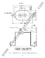
proper latch-holding of the armature. See Figs. 11, 12, and 13 for outlines of the
external capacitor and resistor.
B URDENS
The operating coil burdens
1
i sted Table VII are measured with the relay in the
picked up position, at rated voltage, and are for continuous rating. The common AC
and DC burden table, VIII, applies to all HFA relays except HFA54M and HFA54 N, whose
burdens are listed in Table IX.
TABLE VI I
DC COILS
AC COILS
WATTS
FREQ UENCY
VOLT-
COLD
HOT
CYCLES
AMPERES
WATTS
7.3
6.0
25
10
4
-
-
50
23
9
-
-
60
32
12
TABLE VI II
DC COILS
AC COILS
RATING
RESISTANCE
FREQ UENCY
VOL T-AMPS
250
590
25
55
125
160
50
220
62.5
4 7.5
60
180
4 8
29
-
-
32
12
-
-
24
7.1
-
-
12
2 .1
-
-
6
0.4 9
-
-
Burden ratings and the value of external resistors and capacitors for HFA54M
and HFA54 N are given in Table IX.
6
www
. ElectricalPartManuals
. com


