background image

GEH-1793 

The  AC  voltage  or  DC  current  relays  are  adjusted  to  pick  up  at  70-80  percent  of 

rating  at  rated  frequency. 

The  DC  voltage  relays  are  adjusted  to  pick  up  at  50-60 

percent  of  rating  when  cold. 

After  AC  relays  have  been  continuously  energized  for  a  few  hours  (minimum  four 

hours)  at  rated  voltage,  the  pickup  and  dropout  voltages  increase  by  3. 5  to  7. 5 

percent. 

For  DC  relays,  the  pickup  and  dropout  voltages  increase  by  5  to  10 

percent. 

The  wipe  on  HGA11  relays  exerts  a  contact  pressure  of  35  grams 

� 

10  percent  on 

11 a"  contacts  and  10  grams 

� 

10  percent  on  11b"  contacts. 

C ONS TR U CTION 

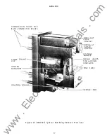
The  HGA11  is  a  molded  case  relay. 

The  various  parts  of  the  relay  can  be  seen 

in  Figure  10. 

The  control  spring  is  used  for  adjusting  the  pickup  and  dropout 

voltage. 

The  function  of  the  voltage  barrier  is  to  avoid  flashover  between  a  pair 

of  electrically  separate,  but  mechanically  coupled  normally  closed  contacts,  or 

between  a  pair  of  normally  open  contacts.  Cover  spring  clips  maintain  spring  force 

against  the  cover  to  hold  the  cover  in  position. 

RECEIVIN G,  HANDLIN G  AND  S TORA G E  

These  relays,  when  not  included  as  part  of  a  control  panel  will  be  shipped  in 

cartons  designed  to  protect  them  against  damage. 

Immediately  upon  receipt  of  a 

relay,  examine  it  for  damage  sustained  in  transit. 

If  damage  resulting  from  rough 

handling  is  evident,  file  a  damage  claim  at  once  with  the  transportation  company  and 
promptly  notify  the  nearest  General  Electric  Apparatus  Sales  Office. 

Reasonable  care  should  be  exercised  in  unpacking  the  relay  in  order  that  none 

of  the  parts  are  damaged  nor  the  adjustments  disturbed. 

If  the  relays  are  not  to  be  installed  immediately,  store  them  in  their  original 

cartons  in  a  place  that  is  free  from  moisture,  dust  and  metallic  chips. 

Foreign 

matter  that  collects  on  the  outside  of  the  case  could  get  inside  when  the  cover  is 

removed,  and  cause  trouble  when  operating  the  relay. 

P ERIODIC  C HECKS  AND  RO UTINE  MAINTENANCE 

In  view  of  the  vital  role  of  relays  in  the  operation  of  a  power  system,  it  is 

important  that  a  periodic  test  program  be  followed. 

The  interval  between  periodic 

checks  will  vary  depending  upon  environment,  type  of  relay  and  the  user's  experience 

with  periodic  testing. 

Until  the  user  has  accumulated  enough  experience  to  select 

the  test  interval  best  suited  to  his  individual  requirements,  the  points  listed 
under 

ACCEP TANCE  TESTS 

should  be  checked  at  an  interval  of  from  one  to  two  years. 

*Indicates Revision 

www 

. ElectricalPartManuals 

. com 
Summary of Contents for HGA11A

Page 1: ...INSTRUCTIONS INSTANTANEOUS AUXILIARY RELAY TYPES HGAllA G H J K P S T V W X GENERAL fj ELECTRIC GEH 1793H Supersedes GEH 1793G w w w E l e c t r i c a l P a r t M a n u a l s c o m ...

Page 2: ... TABLE 4 CHARACTERISTICS ACCEPTANCE TESTS MECHANICAL ADJUSTMENTS PICKUP TEST CONSTRUCTION RECEIVIN G HANDLING AND STORA GE PERIODIC C HECKS AND ROUTINE MAINTENANCE C ONTACT CLEANING RENEWAL PARTS 2 3 3 4 4 5 5 5 5 5 6 6 ifi t 6 6 7 7 7 8 8 w w w E l e c t r i c a l P a r t M a n u a l s c o m ...

Page 3: ...R SEMI FLUSH MOUNTING SEE FIGURE 4 HGA11A G SIMILAR TO HGA11A EXCEPT WITH GLASS SIMILAR TO HGA11A FRONT COVER SEE FIGURE 3 HGA11A N SIMILAR TO HGA11A AND INSPECTED BY SIMILAR TO HGA11A NAVY SEE FIGURE 3 HGA11G FRONT CONNECTED WITH COVER FOR FRONT SIMILAR TO HGA11A MOUNTING SEE FIGURE 8 HGA11H FRONT CONNECTED SURFACE MOUNTED AND SIMILAR TO HGA11A IS AVAILABLE WITHOUT COVER ONLY SEE FIGURE 7 HGA11J ...

Page 4: ...GURE 2 SIMILAR TO HGA11A SIMILAR TO HGA11A The HGA11 relays are available for coil ratings for standard voltages up to 5 7 5 volts for 25 50 o r 60 cycles and up to 250 volts DC The DC relays are also available with coil current ratings up to five amperes The current closing rating of the contacts is 30 amperes The current carrying rating is 12 amperes continuously or 30 amperes for one minute The...

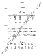
Page 5: ...ng through the coil but the relay is not picked up Xoo is the inductive impedance when the coil is energized but the relay is not picked up The resistive and inductive parts of impedance of coils under picked up conditions are designated as Rpu and Xpu Zoo is the impedance of the relay in dropout condition Zpu is the impedance of the relay in picked up condition TABLE 4 AC COIL BURDENS corr RATrNG...

Page 6: ...at the top of the moving contact carrier This is determined by operating the armature by hand and checking that there is at least 1 16 inch movement of the top edge of the contact carrier after the contacts have made When the armature is operated by hand 11a11 contacts should make within 1 32 inch of each other i e with one contact just making the gap of the other should never be more than 1 32 in...

Page 7: ... cartons designed to protect them against damage Immediately upon receipt of a relay examine it for damage sustained in transit If damage resulting from rough handling is evident file a damage claim at once with the transportation company and promptly notify the nearest General Electric Apparatus Sales Office Reasonable care should be exercised in unpacking the relay in order that none of the part...

Page 8: ...ures cleaning the actual points of contact Knives files abrasive paper or cloth of any kind should not be used to clean relay contacts RENEWAL PARTS Sufficient quantities of renewal parts should be carried in stock to promptly replace any that are worn broken or damaged When ordering renewal parts address the nearest Sales Office of the General Electric Company specify quantity required name of th...

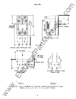
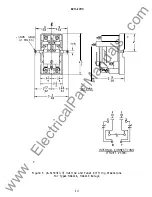
Page 9: ... 8 8 4 l o e 1 fo 2 l lfS PANEL DRI L L ING FRONT V IEW Figure 1 10 32 THREAD _ 3 6 OUTLINE 1B9 12 2 l lfS HGA11K ONLY 2 4 2 8 1 f INTERNAL CONNECTI O NS FOONT VIE W Figure 2 Figures 1 and 2 0104A8573 0 Internal Connections Diagram for Types HGA11A G H J K P S T V W and X Relays 9 w w w E l e c t r i c a l P a r t M a n u a l s c o m ...

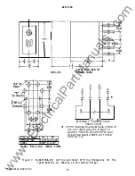
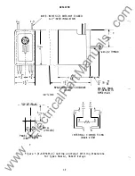
Page 10: ... 318 J PANEL DRI LLJ NG FRONT VIEW 6 7 8 INTERNAL CONNECTIONS BACK VIEW WITH HGAI4A I4J 14K 14N l7A CONTACT 41S NOT USED UNLESS PICKUP 15 RAISED TO 60 DC OR 80 AC OF RATING HGCIIA DOES NOT USED CONTACT 4 Figure 3 K 6077058 20 Outline and Panel Drilling Dimensions for the Types HGAllA G HGAllA N and HGAllV Relays Indicates Revision 10 w w w E l e c t r i c a l P a r t M a n u a l s c o m ...

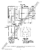
Page 11: ...OO S f r ahi th T l L BJ t N I i 1 I 2 0 f l 7 I llfTE co s lACK VJEI WITH HGA14A 17A CONTACT IS MOT USED ta ESS ICk UP IS RAIS 0 TO 801 CC OR M l AC Of RAT IfiG Figure 4 0104A8557 2 Outline and Panel Drilling Dimensions for the Type HGAllA F Relay Indicates Revision 11 w w w E l e c t r i c a l P a r t M a n u a l s c o m ...

Page 12: ...1 I 4 16 c IIF r _ 1 J 1 5 72 4 8 re 16 SP CE REQlJ t RED TO REMOV UNLESS PANEL COVER Tii I CKNESS 1S OUTL INE SPEC I nED TQP_Qf_llf l A L 1 1 y T 2 l 4 5 5 8 8 1 DRILL 4 2 HOLES PANE L DRI L LING FRONT VIEW 7 8 INTERNA L CONNECTI ONS BACK V lEW Figure 5 K 6375626 4 Outline and Panel Drilling Dimensions for Types HGAllJ HGAllP Relays 12 w w w E l e c t r i c a l P a r t M a n u a l s c o m ...

Page 13: ...LES GEH 1793 OUT L NE r 2 _ ___l 8 7 I NTERNAL CONNECTIONS FRONT VIEW Figure 6 K 6154317 3 Outline and Panel Drilling Dimensions for Types HGA11K HGA11X Relays 13 w w w E l e c t r i c a l P a r t M a n u a l s c o m ...

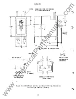
Page 14: ... TO IDNOVE COVER OUTLINE TOP OF RELA Y 1 I V c t5 m 8 8 4 2 HOLES PANEL DRILLING FRONT VIEW 1 2 3 0 2 4 P_j 6 7 8 INTER VAL CONNECTIONS BACK VIEW I J iO _ 8 llD UNLESS PANEL THICKNESS IS SPECIFIED Figure 9 0127A9568 0 Outline and Panel Drilling Dimensions for the Type HGAllT A Relay 16 w w w E l e c t r i c a l P a r t M a n u a l s c o m ...

Page 15: ...CliP HI NGED ARMATURE GEH 1793 NORMALLY OPEN CONTACT NORM ALLY CLOSED CONTACT VOLTAGE BARRIER SPRING LEAVES FOR MOVING CONTACTS POLE PtEC E Figure 10 8042422 Typical HGA Relay Removed from Case 17 w w w E l e c t r i c a l P a r t M a n u a l s c o m ...

Page 16: ...w w w E l e c t r i c a l P a r t M a n u a l s c o m ...

Page 17: ...w w w E l e c t r i c a l P a r t M a n u a l s c o m ...

Page 18: ...ST 12 93 6000 Meter and Control Business Department General Electric Company 205 Great Valley Parkway Malvern PA 79355 w w w E l e c t r i c a l P a r t M a n u a l s c o m ...

Reviews: